In physics, fringes are bands of contrasting brightness or darkness produced by diffraction or interference of radiation with a measurable wavelength.
The objective of this lecture is to give students and others an opportunity to learn about fringes. At the conclusion of reading and studying this lecture students and others should have a well-rounded understanding of the physics of fringes.
Haidinger fringes
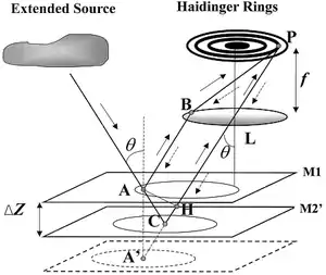
{{fairuse}}Def. "interference fringes produced by light passing through thick glass plates at near-normal incidence"[1] are called Haidinger fringes.
These interference fringes were "named after Wilhelm Karl von Haidinger (1795-1871), [an] Austrian mineralogist".[1]
The diagram on the right demonstrates the generation of Haidinger fringes. By analogy, the distance ΔZ can also refer to the thickness of a flat, polished glass plate with its upper surface acting as a mirror M1, and lower surface acting as an effective reference mirror, M2'. The observation point P as in an optical microscope used in optical mineralogy is above the optical axis of lens L.
"f is the focal length of the lens, AH is a normal from point A to ray CLP, and A' is a mirror image of point A with respect to plane M2'."[2]
"A ray from the source that is incident upon the plane-parallel plate at a small angle θ is reflected by the upper and lower surfaces, M1 and M2', to form parallel rays [AB] and [AC]."[2] These are then focused by lens L to point P in the ring.
Pendellösung fringes
Def. interference fringes produced by radiation passing through thick wedge plates at near-normal incidence are called Pendellösung fringes.
Pendellösung fringes, the name, as coined by the German physicist Paul Peter Ewald, means “spherical solution”.[3]
The "dark and light fringes (Pendellösung fringes) will have a narrower spacing at the edges of the diffraction region and a wider spacing in the centre[.] [The] central part of the fringe turns out to be bent towards the thick part of the wedge. The degree of bending of the fringes depends on L [the source-film distance as in a camera or length to the plane of focus]. In the limit L ⟶ ∞ the fringes are straight, which corresponds to the plane-wave incidence at the Bragg angle [...]. In practice, the fringes are always bent due to L finiteness, and the first fringe broadens out in the centre."[4]
Theoretical fringes
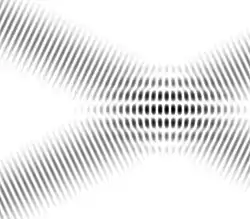
From wave theory, specifically, the interaction of identical waves from at least two sources produces interference fringes, where maxima are separated by the fringe spacing
and df increases with increase in wavelength or decreasing angle θ.
Def.
- a "decorative border",[5]
- a "marginal or peripheral part",[5]
- a "light or dark band formed by the diffraction of light",[5]
- the "peristome or [border]-like appendage of the capsules of most mosses"[6]
is called a fringe.
Neutrons
By bombarding a silicon single crystal wedge with thickness ranging from ~0.3 cm to 1 cm in a slow neutron beam, a series of Pendellösung interference fringes parallel to the thinner edge of the wedge appear within Bragg reflections formed by the diffraction of the neutrons.[7]
Electrons
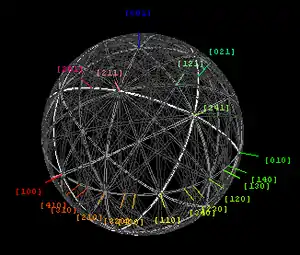
{{free media}}Kikuchi lines pair up to form bands in electron diffraction from single crystal specimens. They serve as "roads in orientation-space" for microscopists not certain at what they are looking. In transmission electron microscopes, they are easily seen in diffraction from regions of the specimen thick enough for multiple scattering.[8] Unlike diffraction spots, which blink on and off as one tilts the crystal, Kikuchi bands mark orientation space with well-defined intersections (called zones or poles) as well as paths connecting one intersection to the next.
Experimental and theoretical maps of Kikuchi band geometry, as well as their direct-space analogs e.g. bend contours, electron channeling patterns, and fringe visibility maps are increasingly useful tools in electron microscopy of crystalline and nanocrystalline materials.[9] Because each Kikuchi line is associated with Bragg diffraction from one side of a single set of lattice planes, these lines can be labeled with the same Miller or reciprocal-lattice indices that are used to identify individual diffraction spots. Kikuchi band intersections, or zones, on the other hand are indexed with direct-lattice indices i.e. indices which represent integer multiples of the lattice basis vectors a, b and c.
Kikuchi lines are formed in diffraction patterns by diffusely scattered electrons, e.g. as a result of thermal atom vibrations.[10] The main features of their geometry can be deduced from a simple elastic mechanism proposed in 1928 by Seishi Kikuchi,[11] although the dynamical theory of diffuse inelastic scattering is needed to understand them quantitatively.[12]
In x-ray scattering these lines are referred to as Kossel lines[13] (named after Walther Kossel).
Opticals
"A complete theory of Maker fringes in nonabsorbing isotropic and uniaxial crystals has been derived which includes all the corrections necessary for making precise determinations of nonlinear optical co‐efficients. These corrections include finite beamwidth effects and multiple reflection corrections. Comparison of this theory with extensive experimental data on the Maker fringes in quartz, ADP, and KDP shows agreement to within the experimental accuracy of about 5% on the Maker fringe envelopes and to better than 1% on the coherence lengths. We conclude from this study that a careful analysis of Maker fringes can yield precise values of the nonlinear optical coefficients and coherence lengths in isotropic and uniaxial crystals. This is of great importance in establishing accurate and reliable standards in the field of nonlinear optics."[14]
Visuals
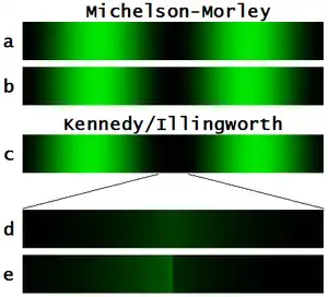
{{free media}}With respect to the image on the right: (a) Michelson-Morley interference pattern in monochromatic mercury light, with a dark fringe precisely centered on the screen, (b) the fringes have been shifted to the left by 1/100 of the fringe spacing, (c) a small step in one mirror causes two views of the same fringes to be spaced 1/20 of the fringe spacing to the left and to the right of the step, (d) a telescope has been set to view only the central dark band around the mirror step (note the symmetrical brightening about the center line), (e) the two sets of fringes have been shifted to the left by 1/100 of the fringe spacing producing an abrupt discontinuity in luminosity is visible across the step.
Infrareds
{{fairuse}}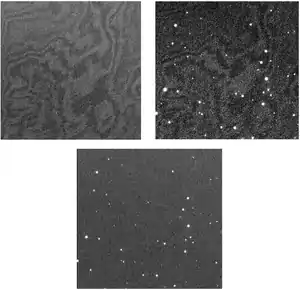
{{fairuse}}"Fringing in CCD images is troublesome from the aspect of photometric quality and image flatness in the final reduced product. Additionally, defringing during calibration requires the inefficient use of time during the night to collect and produce a "supersky" fringe frame. The fringe pattern observed in a CCD image for a given near-IR filter is dominated by small thickness variations across the detector, with a second-order effect caused by the wavelength extent of the emission lines within the bandpass that produce the interference pattern."[15]
Essentially "any set of emission lines that generally match the wavelength coverage of the night-sky emission lines within a bandpass will produce an identical fringe pattern."[15]
"The production of constructive and destructive interference patterns can cause substantial quantum efficiency variations in thinned CCDs as long-wavelength light is multiply reflected between the front and back surfaces. Fringing begins to be an issue for CCDs when the absorption depth within the silicon becomes comparable with the thickness of the CCD. This occurs for optical wavelengths of ~700 nm or longer, for which the light is internally reflected several times before finally being absorbed (Lesser 1990; Howell 2006)."[15]
"To eliminate the need to use valuable observing time during the night to collect a set of deep-sky exposures in order to produce a "supersky" fringe frame, we used afternoon flat-field exposures of a neon lamp to obtain fringe frames with high signal-to-noise ratios (S/N). The fringe pattern produced in a CCD image is shown to consist of an average pattern from all the emission lines present within a given filter bandpass; thus, the neon emission-line source (Ne lamp) provides a match to the fringe pattern produced by night-sky emission on a filter-by-filter basis. The collection of daytime neon fringe flats provides a fast, efficient method to produce fringe frames, and the defringed CCD images show a complete removal of the night-sky effects."[15]
"Fringing most notably occurs within a CCD when near-monochromatic light is incident on the detector. Spectroscopic observations are prone to fringing, due to their collection of dispersed light placing individual wavelengths across pixels (e.g., Malumuth et al. 2003). Direct images also suffer from fringing (e.g., Gullixson 1992), especially for narrowband observations, primarily due to the bright night-sky emission lines from atmospheric OH molecules. Auroral [O I] emission near 630 nm can also be strong at times and partake in fringe production. Reducing fringing in a CCD can be done by controlling the CCD thinning process to a high level of flatness and by applying an antireflection coating to the back of a thinned CCD. Both of these solutions provide mitigation by reducing the fringe amplitude from near 50% or more to 2% or less."[15]
The "average fringe pattern produced on a CCD image by the summation of all the OH emission lines within a given bandpass can be well approximated by essentially any set of emission lines that generally have the same wavelength distribution within a given bandpass."[15]
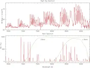
The top spectrum in the figures on the right of the night-sky covering the near-IR (Massey & Foltz 2000) has large emission-line bands due to the OH molecule in the Earth’s atmosphere.[15]
"These emission lines are the primary cause of CCD fringing."[15]
The bottom figure shows the emission-line spectrum of a neon lamp shown the same spectral region.[15]
Neon also has groups of emission lines within this region that will provide the same fringe pattern on a CCD as OH emission.[15]
Broadband I and z bandpasses are indicated.[15]
The images on the left contain: (Top left) I-band neon fringe flat field. (Top right) Same CCD section showing a nighttime I-band image of a star field taken with strong OH emission. (Bottom) Same section in the final reduced image showing the complete removal of the CCD fringes.[15]
Gravitationals
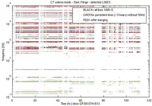
{{fairuse}}In preparation for the detection of gravitational radiation at the Virgo interferometer a series of runs was made to measure and identify vibrational frequencies and their origins. One such run "C7" was "work on the detection and investigation of the origin of the frequency lines in the Virgo dark fringe data from run C7. A number of data analysis techniques and experimental methods (in the laboratory) [were] used to identify and characterize these noise lines. [A] first selection of frequency lines [was generated]. Line candidates also come as the by-product of the analysis pipeline of the periodic signal searches (PSS) performed by the Virgo pulsar search group."[16]
Some "lines [were identified] as originating from the WE and NE air conditioning[.] Other lines that were identified include: mirror modes and violin modes of mirror wires [...], includes a measurement of ring-down decay time [...], sidebands of calibration lines [...], and lines due to the residual aliasing in the 4kHz down-sampled data [...]. [One] preliminary list of persistent frequency peaks ("lines") [was produced] by applying the line search algorithm [...] to the dark fringe photodiode signal (channel Pr_B1_ACp). [The] complete dataset of C7 science mode data (about 100 hours) [was processed] by requiring the quality flag Qc_Moni_ScienceMode to be one."[16]
In the image on the right is a time-frequency "map of frequency peaks detected by the search algorithm [...] applied to C7 dark fringe science mode data segments (black). There were 61516 frequency peaks above the [signal to noise resolution] SNR threshold, corresponding to 772 different frequencies. This reduces to 155 persistent ones [...], and finally reduces to 71 lines candidates (plus 18 50Hz harmonics) after merging nearby frequencies."[16]
Hypotheses
- The formal term fringes is used for detectable variations, including second order harmonics.
See also
References
- 1 2 Random House Dictionary (2018). Haidinger fringes. Dictionary.com Unabridged, Random House, Inc. Retrieved 2018-02-23.
- 1 2 Wei Wang, Hirokazu Kozaki, Joseph Rosen, and Mitsuo Takeda (1 April 2002). "Synthesis of longitudinal coherence functions by spatial modulation of an extended light source: a new interpretation and experimental verifications". Applied Optics 41 (10): 1962-1971. https://pdfs.semanticscholar.org/2801/2c300e5356947a2d684ec974968e11afccdb.pdf. Retrieved 2018-2-24.
- ↑ Oxford (2008). Lecture 5 — Scattering geometries (PDF). Oxford, UK: Oxford University. Retrieved 2018-03-01.
- ↑ V. V. Aritov, V. I. Polovinkina, A. M. Afanas'ev, and V. G. Kohn (1980). "Pendellösung Fringes for X-ray Spherical-Wave Diffraction in a Perfect Crystal". Acta Crystallographica A36: 1002-13. doi:10.1107/S0567739480002045. http://kohnvict.narod.ru/articles/023.pdf. Retrieved 2018-2-26.
- 1 2 3 SemperBlotto (13 February 2005). "fringe". San Francisco, California: Wikimedia Foundation, Inc. Retrieved 2018-02-24.
- ↑ Equinox (12 July 2013). "fringe". San Francisco, California: Wikimedia Foundation, Inc. Retrieved 2018-02-24.
- ↑ C.G. Shull (December 1968). "Observation of Pendellösung Fringe Structure in Neutron Diffraction". Physical Review Letters 21 (23): 1585-1589. doi:10.1103/PhysRevLett.21.1585. http://adsabs.harvard.edu/abs/1968PhRvL..21.1585S. Retrieved 2018-2-26.
- ↑ David B. Williams; C. Barry Carter (1996). Transmission electron microscopy: A textbook for materials science. Plenum Press, NY. ISBN 0-306-45324-X.
- ↑ K. Saruwatari; J. Akai; Y. Fukumori; N. Ozaki; H. Nagasawa; T. Kogure (2008). "Crystal orientation analyses of biominerals using Kikuchi patterns in TEM". J. Mineral. Petrol. Sci. 103: 16–22.
- ↑ Earl J. Kirkland (1998). Advanced computing in electron microscopy. Plenum Press, NY. p. 151. ISBN 0-306-45936-1.
- ↑ S. Kikuchi (1928). "Diffraction of Cathode Rays by Mica". Japanese Journal of Physics 5: 83–96.
- ↑ P. Hirsch; A. Howie; R. Nicholson; D. W. Pashley; M. J. Whelan (1977). Electron microscopy of thin crystals. Butterworths/Krieger, London/Malabar FL. ISBN 0-88275-376-2.
- ↑ R. W. James (1982). "Chapter VIII". The Optical Principles of the Diffraction of X-Rays'. Ox Bow Press, Woodbridge, Connecticut. ISBN 0-918024-23-4.
- ↑ J. Jerphagnon and S. K. Kurtz (1970). "Maker Fringes: A Detailed Comparison of Theory and Experiment for Isotropic and Uniaxial Crystals". Journal of Applied Physics 41 (4): 1667. doi:10.1063/1.1659090. http://aip.scitation.org/doi/abs/10.1063/1.1659090. Retrieved 2017-12-29.
- 1 2 3 4 5 6 7 8 9 10 11 12 Steve B. Howell (17 February 2012). "Fringe Science: Defringing CCD Images with Neon Lamp Flat Fields". Publications of the Astronomical Society of the Pacific 124 (913): 263-67. http://iopscience.iop.org/article/10.1086/664741/meta. Retrieved 2017-12-26.
- 1 2 3 I. Fiori, E. Cuoco, F. Paoletti, N. Christensen, and G. Vajente (11 November 2006). "Analysis of spectral lines in run C7". VIR-NOT-EGO-1390-339 (1): 1-29. http://citeseerx.ist.psu.edu/viewdoc/download?doi=10.1.1.546.8389&rep=rep1&type=pdf. Retrieved 2018-2-25.