| Subject classification: this is a physics resource. |
Wikiversity resources
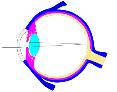
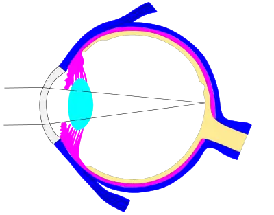
The incredible editable eye
| Click to view an svg file that is easily edited in order to study the human eye |
|---|
|
Sister links and other resources
A collapsable list of sister links is shown to the right. It is not yet complete -- feel free to add links to Wikipedia/Wikibooks.
- See also this collection of images: Gallery_and_resources
Important external links on optics
- Physics Classroom - Ray optics
- Phet - Geometrical optics
- Hyperphysics - Light and vision
- Optics Express Optics open access journal
From Wikipedia
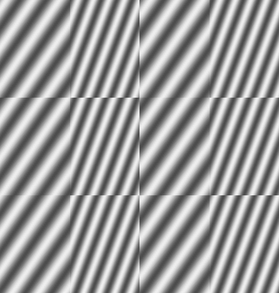
Geometrical optics, or ray optics, describes light propagation in terms of "rays". The "ray" in geometric optics is a concept that permits us to view light in an extremely primitive version of the "particle picture" of quantum mechanics (primitive because Einsteins "E=hf" is never needed or used). Rays bend (and may split in two) at any interface, may curve in a medium where the refractive index changes, and may be absorbed and reflected. This is a significant simplification of optics that fails to account for optical effects such as diffraction and interference. The approximation tends to be valid when the wavelength is very small compared with the size of structures with which the light interacts.
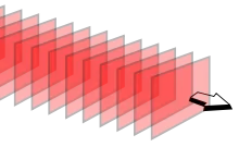
The image to the right shows how waves can form a ray if the wavelength is very small.
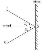
Reflection refers to the bouncing of light off an object in a fashion that resembles how a ball might bounce off a wall (neglecting any effects due to the fact that the ball is spinning). Glossy surfaces such as mirrors reflect light in a simple, predictable way: (1) The incident and reflected rays lie in a single plane, and (2) the angle between the reflected ray and the surface normal is the same as that between the incident ray and the normal.
- Definition of "normal". The surface normal, a line perpendicular to the surface at the point where the ray hits.
This law applies to flat mirrors, as well as mirrors with curved surfaces (examples of curved surfaces include parabolic and spherical).
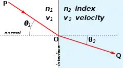
Refraction occurs when light travels through an area of space that has a changing index of refraction. The simplest case of refraction occurs when there is an interface between a uniform medium with index of refraction and another medium with index of refraction . In such situations, Snell's Law describes the resulting deflection of the light ray:
where and are the angles between the normal (to the interface) and the incident and refracted waves, respectively. As discussed in Wikipedia, the index of refraction is closely related to the speed of the wave in the material: n=c/v, where c is the speed of light in vacuum and v is the speed of light in the medium.
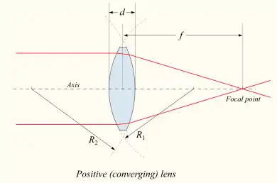
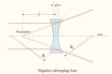
- A device which produces converging or diverging light rays due to refraction is known as a lens. Thin lenses produce focal points on either side that can be modeled using the lensmaker's equation. In general, two types of lenses exist: convex lenses, which cause parallel light rays to converge, and concave lenses, which cause parallel light rays to diverge.
The paraxial approximation
The paraxial approximation can be used to derive simple equations involving lenses. A statement of the approximation involves the optical axis, which is a line that passes through the center of each lens and is oriented in a direction normal to the surface of the lens (at the center). The paraxial approximation is valid for rays that make a small angle to the optical axis of the system, and also lie close to the optical axis, throughout the system.
Further simplification occurs when we assume that the lenses are sufficiently thin; this is known as the thin lens approximation. In this approximation, two points, called focal points, are situated at equal lengths to the left and right of the lens. Focal points are denoted with the capital letter F, while the distance from the focal point to the center of a then lens is called the focal length, denoted by the lower case f.
Warning: The point where all the ray coming from a given point on an object is called the image, which is generally not the same as the focal point of a lens.
Viewing optics in two dimensions
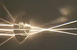
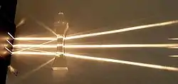
It is instructive to use a ray optics kit to view lenses. A description of these images can be found on Wikipedia's Lens. Note how reality is a bit different from the simple model.
The three easy rays and the thin lens formula
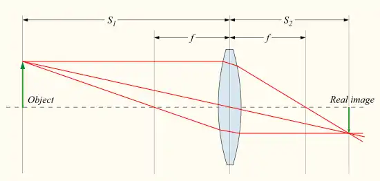
The detailed prediction of how images are produced by these lenses can be made using either ray-tracing methods or equations. Thin lenses follow a simple equation that determines the location of the images given a particular focal length () and object distance ():
where is the distance associated with the image and is considered by convention to be negative if on the same side of the lens as the object and positive if on the opposite side of the lens. The focal length f is considered negative for concave lenses.
Real image for converging lens occurs when S1 > f >0
It is customary with lenses to assume that the light travels from left to right, and in such cases, the convention is that the object distance S_1 is positive. If the lens is converging, f>0, and if S1>f, the equation above yields a value of S2 that is positive, which means that the image is to the right of the lens. Such an image is called a real image, because rays actually converge to that point.
Virtual image for converging lens occurs when 0 <S1 < f
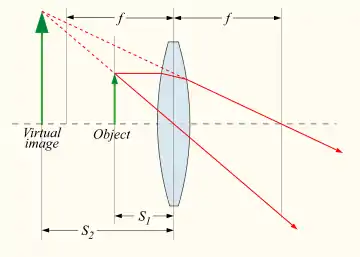
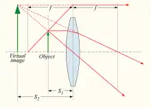
If the object is moved closer to the lens than it's own focal length, the equations predict that S2 < 0. In this case the image is on the left of the lens. In other words, the rays on the right side of the lens are diverging as if they originated at a point to the left of the lens. Such an image is called a virtual image. When a magnifying glass is used in this way, it is impossible to converge all the light from a source to a single point. This situation does describe the use of a magnifying glass or reading glasses to better see something that is small and/or too close to the eye for comfortable viewing.
In this case it is worth noting that the rays continue to diverge after passing through the converging lens. But they diverge less. The question of whether a converging lens causes the rays to actually converge after passing through the lens is easy to answer:
- If the object distance is greater than the focal length of a converging lens (S1 > f > 0) the converging lens causes the rays to converge.
- If the object distance is less than the focal length converging lens (f > S1 0) the rays continue to diverge, but diverge less.
- If the object distance equals the focal length of a converging lens (S1 = f > 0) the rays neither converge nor diverge, but emerge parallel to each other.
Thoughts on infinity
If the rays are parallel, they are said to meet at infinity. If S1 = f , then our equation (1/S1 + 1/S2 = 1/f) yields what may seem like the meaningless result, S2 = 1/0. This is a good place to mention that "infinity" has a practical value. We can give meaning to this equation to the loosely defined mathematically statement,
- ,
| click here for a slightly more sophisticated discussion |
|---|
|
and where is commonly used "shorthand" for an infinitesimally small number either slightly larger or smaller than zero. This idea is also sometimes represented as or . It seems odd that zero-plus is almost equal to zero-minus, while plus and minus infinity seems far apart. See also Wikipedia:point at infinity. |
by noting that in practice one cannot put the image exactly at a given point, with 0% error. If "0" is a very small positive number, then 1/"0" is very large and positive. If "0" is very close to zero, but negative, then 1/"0" approaches negative infinity. It is customary to use superscripts to indicate the sign of a number that is approaching zero: 0- is negative and 0+ is positive. Physically, the two infinities (positive and negative) are also "nearly equal" in that both represent nearly parallel rays that either slightly diverge or slightly converge.[1]
Virtual images from a diverging lens when f < 0
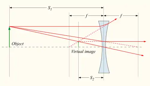
The formulas above may also be used for negative (diverging) lens by using a negative focal length (f), but for these lenses only virtual images can be formed.
More from Wikipedia
For students wishing to model the eye using the editable svg file, the Lensmaker's equation states that
There is also a more general version of the formula if the lens is placed inside a medium other than air:
A number of consequences of these rules are discussed in Wikipedia's Geometrical optics
