Amplifier
An electronics device that generates an output voltage equals to the product of input voltage multiply by an amplification factor

There are two types of amplifier
- DC amplifier
- AC amplifier
DC amplifier
Transformer Amplifier
Non inverting Amplifier

With
- .


Inverting Amplifier

With
- .

Transistor Amplier
Non inverting Amplifier

With
- .

Inverting Amplifier

With
- .

Operational Amplifier
We begin these examples with that of the differential amplifier, from which many of the other applications can be derived, including the inverting, non-inverting, and summing amplifier, the voltage follower, integrator, differentiator, and gyrator.
Differential amplifier (difference amplifier)
Amplifies the difference in voltage between its inputs.
- The name "differential amplifier" must not be confused with the "differentiator," which is also shown on this page.
- The "instrumentation amplifier," which is also shown on this page, is a modification of the differential amplifier that also provides high input impedance.
The circuit shown computes the difference of two voltages, multiplied by some gain factor. The output voltage:

Or, expressed as a function of the common mode input Vcom and difference input Vdif

the output voltage is

In order for this circuit to produce a signal proportional to the voltage difference of the input terminals, the coefficient of the Vcom term (the common-mode gain) must be zero, or

With this constraint If you think of the left-hand side of the relation as the closed-loop gain of the inverting input, and the right-hand side as the gain of the non-inverting input, then matching these two quantities provides an output insensitive to the common-mode voltage of and .</ref> in place, the common-mode rejection ratio of this circuit is infinitely large, and the output


where the simple expression Rf / R1 represents the closed-loop gain of the differential amplifier.
The special case when the closed-loop gain is unity is a differential follower, with:

Inverting amplifier

An inverting amplifier is a special case of the differential amplifier in which that circuit's non-inverting input V2 is grounded, and inverting input V1 is identified with Vin above. The closed-loop gain is Rf / Rin, hence
- .

The simplified circuit above is like the differential amplifier in the limit of R2 and Rg very small. In this case, though, the circuit will be susceptible to input bias current drift because of the mismatch between Rf and Rin.
To intuitively see the gain equation above, calculate the current in Rin:

then recall that this same current must be passing through Rf, therefore (because V− = V+ = 0):

A mechanical analogy is a seesaw, with the V− node (between Rin and Rf) as the fulcrum, at ground potential. Vin is at a length Rin from the fulcrum; Vout is at a length Rf. When Vin descends "below ground", the output Vout rises proportionately to balance the seesaw, and vice versa.
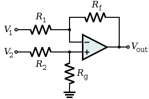
Non-inverting amplifier

A non-inverting amplifier is a special case of the differential amplifier in which that circuit's inverting input V1 is grounded, and non-inverting input V2 is identified with Vin above, with R1 ≫ R2. Referring to the circuit immediately above,
- .

To intuitively see this gain equation, use the virtual ground technique to calculate the current in resistor R1:

then recall that this same current must be passing through R2, therefore:

Unlike the inverting amplifier, a non-inverting amplifier cannot have a gain of less than 1.
A mechanical analogy is a class-2 lever, with one terminal of R1 as the fulcrum, at ground potential. Vin is at a length R1 from the fulcrum; Vout is at a length R2 further along. When Vin ascends "above ground", the output Vout rises proportionately with the lever.
The input impedance of the simplified non-inverting amplifier is high, of order Rdif × AOL times the closed-loop gain, where Rdif is the op amp's input impedance to differential signals, and AOL is the open-loop voltage gain of the op amp; in the case of the ideal op amp, with AOL infinite and Rdif infinite, the input impedance is infinite. In this case, though, the circuit will be susceptible to input bias current drift because of the mismatch between the impedances driving the V+ and V− op amp inputs.
Voltage follower (unity buffer amplifier)

Used as a buffer amplifier to eliminate loading effects (e.g., connecting a device with a high source impedance to a device with a low input impedance).
- (realistically, the differential input impedance of the op-amp itself, 1 MΩ to 1 TΩ)


Due to the strong (i.e., unity gain) feedback and certain non-ideal characteristics of real operational amplifiers, this feedback system is prone to have poor stability margins. Consequently, the system may be unstable when connected to sufficiently capacitive loads. In these cases, a lag compensation network (e.g., connecting the load to the voltage follower through a resistor) can be used to restore stability. The manufacturer data sheet for the operational amplifier may provide guidance for the selection of components in external compensation networks. Alternatively, another operational amplifier can be chosen that has more appropriate internal compensation.
Summing amplifier
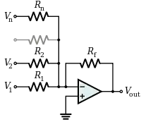
A summing amplifier sums several (weighted) voltages:

- When , and independent


- When


- Output is inverted
- Input impedance of the nth input is ( is a virtual ground)


Instrumentation amplifier
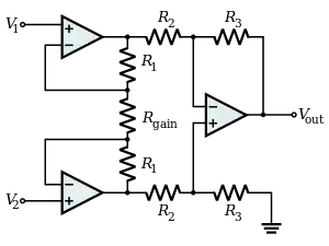
Combines very high input impedance, high common-mode rejection, low DC offset, and other properties used in making very accurate, low-noise measurements
- Is made by adding a non-inverting buffer to each input of the differential amplifier to increase the input impedance.