Another Useless Architecture (AUA) is a RISC microprocessor architecture developed by Jakob Wilhelm, Stefan Rottensteiner and Stefan Tauner as a course project for the Computer Architecture Lab at the Vienna University of Technology in winter 2008/2009. It has been implemented in VHDL and tested in a Cyclone II FPGA from Altera on a DE2 development board from Terasic Technology.
Description
AUA is a 16bit RISC architecture providing 32 registers apparently having similarities to MIPS. E.g. MIPS branches are supported by individual compare and branch instructions (i.e. you have to compare two values/registers and use the result as input for the branch decision). The branch delay is 0 for untaken and 1 cycle for taken branches. The branch decision and branch address calculation is done in the ID stage. An additional cycle is lost if the branch uses the result of the preceding instruction. It is not possible to circumvent this stall with forwarding as this would introduce a new longest path (from the ID/EX pipeline registers through the alu, through the branch decision unit in ID, to the PC register in IF). The EX stage forwards its results to resolve data hazards in all other instruction sequences though (i.e. if instruction uses the (EX) result of instruction as (EX) input). We used on-chip memory of the FPGA (M4K blocks) for the register file. As the memory requires registered inputs, this registers can be regarded as pipeline registers for the WB stage. To be able to read two registers (the two operands) and write one (the result of the previous instruction), we had to duplicate the register file into two "simple dual-port mode" memories. Another possibility would be to clock the memory twice as fast, but we did prefer a single clock domain. In dual-port mode the on-chip memory has a latency of 1.5 cycles, which made another forwarding necessary if instr. uses the result of instr. . Beside the branch stall, where IF and (partially) ID get locked, the EX stage needs to lock all stages, when a load/store operation takes more than one cycle.


Memory and I/O
Instructions, data and memory-mapped I/O devices all share the same address space. The MMU is responsible for handling all memory transactions and transfers the data to the instruction cache and from/to the load/store unit in the EX stage. LD/ST transactions have priority over instruction fetches, so that the pipeline can progress normally. IF will schedule a nop if it is blocked because the current instr. is not available.
The MMU can access on-board SRAM, on-chip ROM (e.g. for a bootloader) and an unlimited number of SimpCon devices. They all share the same address space, which is divided in parts by the MMU. The SimpCon bus is specified as a point-to-point connection, but it is possible to create a shared SimpCon bus by connecting every SimpCon slave to an independant 'RD' and 'WR' line. In the opposite direction (i.e. from the SC slave to the master) it is necessary to multiplex 'WR_DATA' and 'RDY_CNT', because there are no tri-state buses in FPGAs (see Tri-State Buses in Altera Devices). Both tasks are fullfilled by a multiplexer process in the top entity. It matches the 'ADDRESS' similar to IP network masks and selects the corresponding signals.
Pipeline stages
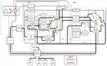
AUA has three stages (four if you include write-back): IF, ID, EX/MEM. IF requests the instruction at the current address/PC from the cache/MMU and extracts the various fields (opcode, immediate, operand and destinstation register addresses). These fields get registered and feed into ID.
The immediate field gets expanded and sign extended before a logic block controls a mux according to the current opcode to choose the correct form of immediate or drop it altogether in favor of a value read from the register file. ID also decides, if a branch is taken and if so, which address is next to be fetched by IF. It is not possible to read the PC directly, but to support returning from functions, ID can store the PC into a register by scheduling an ordinary MOV and overriding the source operand with the current PC value.
EX contains the ALU and a small control curcuit to process LD/ST instructions in cooperation with the MMU. The result of either the ALU or the MMU is selected and transfered to the register file (through the ID unit). If the destination is the zero register, EX enforces a value of 0 to not alter the register.
Instruction Cache
It is possible to plug in different instruction cache implementations between the IF stage and the MMU. Currently a dummy cache (that caches nothing and just connects the signals between IF and the MMU) and a generic direct-mapped cache are provided.
The number of lines cached by the direct-mapped cache can be configured. Currently only on word per cache line is working, because there is no prefetching done by the MMU. It is planned to change this soon. It is also planned to use on-chip memory instead of dedicated logic registers for the cache.
Instruction Set Architecture
The ISA of AUA is typical for a RISC. It was designed with the decoding in mind: All types of fields (opcode, immediates etc.) have a fixed location in the fixed-sized instruction word of 16b. One attribute of our architecture particularly constrained the design of the ISA: We decided that we want 32 registers. This means that out of the 16 bits of one instruction word, 5 bits are needed to address a register.
Most commands need two input registers and one destination register. We use 2 address encoding, where one source register is used as the destination too. This leaves us with at most 6 bits for the opcode, or a maximum of 64 instructions. This number gets reduced by the ldi instruction, because 8b are needed for the immediate itself plus 5b for the destination register, leaving 3b for the ldi opcode. Or in other words are wasted for a part of the immediate value. These 3 bits can't be used for other instructions. Since we could not think of 56 useful instructions anyway, we introduced another type of instruction, that uses immediates.(addi,muli) These use 7 bits to encode the immediate, wasting 2b of opcode space each. So the total number of instructions is limited to .


Instructions
The following table lists all instructions currently implemented in hardware (see the pseudo instruction section below for the rest). There are still some white spots, which are reserved for later use. Cells filled with a s form an encoded source register. d, i likewise for destination registers and immediates. a denotes that the memory address (e.g. for a branch) is taken from the register encoded by these cells. The Imm. column indicates how immediates are interpreted (e.g. the values used with branches get sign-extended and can represent forward as well as backward (=negative) jumps).
| Mnemo. | Imm. | OP B | OP A | hex op | notes | ||||||||||||||
|---|---|---|---|---|---|---|---|---|---|---|---|---|---|---|---|---|---|---|---|
| 15 | 14 | 13 | 12 | 11 | 10 | 9 | 8 | 7 | 6 | 5 | 4 | 3 | 2 | 1 | 0 | ||||
| ldi | unsigned | 0 | 0 | 0 | i | i | i | i | i | i | i | i | d | d | d | d | d | 0x00-0x07 | |
| 0 | 0 | 1 | 0 | 0 | 0 | 0x08 | |||||||||||||
| 0 | 0 | 1 | 0 | 0 | 1 | 0x09 | |||||||||||||
| 0 | 0 | 1 | 0 | 1 | 0 | 0x0A | |||||||||||||
| 0 | 0 | 1 | 0 | 1 | 1 | 0x0B | |||||||||||||
| 0 | 0 | 1 | 1 | 0 | 0 | 0x0C | |||||||||||||
| jmpl | 0 | 0 | 1 | 1 | 0 | 1 | a | a | a | a | a | 0x0D | |||||||
| brez | 0 | 0 | 1 | 1 | 1 | 0 | a | a | a | a | a | s | s | s | s | s | 0x0E | ||
| brnez | 0 | 0 | 1 | 1 | 1 | 1 | a | a | a | a | a | s | s | s | s | s | 0x0F | ||
| brezi | signed | 0 | 1 | 0 | 0 | i | i | i | i | i | i | i | s | s | s | s | s | 0x10-0x13 | |
| brnezi | signed | 0 | 1 | 0 | 1 | i | i | i | i | i | i | i | s | s | s | s | s | 0x14-0x17 | |
| addi | signed | 0 | 1 | 1 | 0 | i | i | i | i | i | i | i | d | d | d | d | d | 0x18-0x1B | sets carry |
| muli | signed | 0 | 1 | 1 | 1 | i | i | i | i | i | i | i | d | d | d | d | d | 0x1C-0x1F | |
| add | 1 | 0 | 0 | 0 | 0 | 0 | s | s | s | s | s | d | d | d | d | d | 0x20 | sets carry | |
| addc | 1 | 0 | 0 | 0 | 0 | 1 | s | s | s | s | s | d | d | d | d | d | 0x21 | sets carry | |
| sub | 1 | 0 | 0 | 0 | 1 | 0 | s | s | s | s | s | d | d | d | d | d | 0x22 | sets carry | |
| subc | 1 | 0 | 0 | 0 | 1 | 1 | s | s | s | s | s | d | d | d | d | d | 0x23 | sets carry | |
| mul | 1 | 0 | 0 | 1 | 0 | 0 | s | s | s | s | s | d | d | d | d | d | 0x24 | ||
| mulu | 1 | 0 | 0 | 1 | 0 | 1 | s | s | s | s | s | d | d | d | d | d | 0x25 | ||
| mulh | 1 | 0 | 0 | 1 | 1 | 0 | s | s | s | s | s | d | d | d | d | d | 0x26 | ||
| mulhu | 1 | 0 | 0 | 1 | 1 | 1 | s | s | s | s | s | d | d | d | d | d | 0x27 | ||
| or | 1 | 0 | 1 | 0 | 0 | 0 | s | s | s | s | s | d | d | d | d | d | 0x28 | ||
| and | 1 | 0 | 1 | 0 | 0 | 1 | s | s | s | s | s | d | d | d | d | d | 0x29 | ||
| xor | 1 | 0 | 1 | 0 | 1 | 0 | s | s | s | s | s | d | d | d | d | d | 0x2A | ||
| not | 1 | 0 | 1 | 0 | 1 | 1 | s | s | s | s | s | d | d | d | d | d | 0x2B | ||
| neg | 1 | 0 | 1 | 1 | 0 | 0 | s | s | s | s | s | d | d | d | d | d | 0x2C | ||
| asr | 1 | 0 | 1 | 1 | 0 | 1 | s | s | s | s | s | d | d | d | d | d | 0x2D | ||
| lsl | 1 | 0 | 1 | 1 | 1 | 0 | s | s | s | s | s | d | d | d | d | d | 0x2E | ||
| lsr | 1 | 0 | 1 | 1 | 1 | 1 | s | s | s | s | s | d | d | d | d | d | 0x2F | ||
| lsli | unsigned | 1 | 1 | 0 | 0 | 0 | 0 | i | i | i | i | d | d | d | d | d | 0x30 | ||
| lsri | unsigned | 1 | 1 | 0 | 0 | 0 | 1 | i | i | i | i | d | d | d | d | d | 0x31 | ||
| scb | unsigned | 1 | 1 | 0 | 0 | 1 | 0 | k | i | i | i | i | d | d | d | d | d | 0x32 | k=set/!clear |
| roti | unsigned | 1 | 1 | 0 | 0 | 1 | 1 | k | i | i | i | i | d | d | d | d | d | 0x33 | k=left/!left |
| cmplt | 1 | 1 | 0 | 1 | 0 | 0 | s | s | s | s | s | s | s | s | s | s | 0x34 | ||
| cmpltu | 1 | 1 | 0 | 1 | 0 | 1 | s | s | s | s | s | s | s | s | s | s | 0x35 | ||
| cmplte | 1 | 1 | 0 | 1 | 1 | 0 | s | s | s | s | s | s | s | s | s | s | 0x36 | ||
| cmplteu | 1 | 1 | 0 | 1 | 1 | 1 | s | s | s | s | s | s | s | s | s | s | 0x37 | ||
| cmpe | 1 | 1 | 1 | 0 | 0 | 0 | s | s | s | s | s | s | s | s | s | s | 0x38 | ||
| cmpei | unsigned | 1 | 1 | 1 | 0 | 0 | 1 | i | i | i | i | i | d | d | d | d | d | 0x39 | |
| 1 | 1 | 1 | 0 | 1 | 0 | 0x3A | |||||||||||||
| mov | 1 | 1 | 1 | 0 | 1 | 1 | s | s | s | s | s | d | d | d | d | d | 0x3B | ||
| ld | 1 | 1 | 1 | 1 | 0 | 0 | a | a | a | a | a | d | d | d | d | d | 0x3C | ||
| ldb | 1 | 1 | 1 | 1 | 0 | 1 | a | a | a | a | a | d | d | d | d | d | 0x3D | ||
| st | 1 | 1 | 1 | 1 | 1 | 0 | a | a | a | a | a | s | s | s | s | s | 0x3E | ||
| stb | 1 | 1 | 1 | 1 | 1 | 1 | a | a | a | a | a | s | s | s | s | s | 0x3F | ||
| 15 | 14 | 13 | 12 | 11 | 10 | 9 | 8 | 7 | 6 | 5 | 4 | 3 | 2 | 1 | 0 | ||||
| OP B | OP A | ||||||||||||||||||
ldi – Load Immediate (signed, byte)
| Operation | Syntax | Operands |
| Rd <-- Imm(byte) | LDI Rd, Imm | Imm ... 8bit signed Immediate |
| Rd ... Destinationregister | ||
Load an 8 bit signed immediate to the Low Byte of Register Rd
jmpl – Jump and Link
| Operation | Syntax | Operands |
| PC <-- Addr, R31 <-- PC | JMPL Rs | Rs... Register contains the address to jump |
Jump to the Addr
brez – Branch if Equal Zero
| Operation | Syntax |
| if Rs = 0 then PC <-- Addr else PC <-- PC + 16 | BREZ Addr, Rs |
Branch to the Addr if the content of Rs is equal to zero
brnez – Branch if Not Equal Zero
| Operation | Syntax |
| if Rs != 0 then PC <-- Addr else PC <-- PC + 16 | BRNEZ Addr, Rs |
Branch to the Addr if the content of Rs is not equal to zero
brezi – Branch if Equal Zero Immediate
| Operation | Syntax | Operands |
| if Imm = 0 then PC <-- Addr else PC <-- PC + 16 | Brezi Addr, Imm | Imm ... 7 bit signed Immediate |
Branch to the Addr if the imm is equal to zero
brnezi – Branch if Not Equal Zero Immediate
| Operation | Syntax | Operands |
| if Imm != 0 then PC <-- Addr else PC <-- PC + 16 | BRNEZI Addr Imm | Imm...7 bit signed Immediate |
Branch to the Addr if the imm is not equal to zero
Addi – Add Immediate
| Operation | Syntax | Operands |
| Rd <-- Rd + Imm | ADDI Rd, Imm | Imm ... 7 bit signed Immediate |
Add an 7 bit signed Immediate to Rd and wirite the result back to Rd
Muli – Multiply Immediate
| Operation | Syntax | Operands |
| Rd <-- Rd * Imm | MULI Rd,Imm | Imm ... 7 bit signed Immediate |
Multiply an 7 bit signed Immediate with Rd and wirite the result back to Rd After execution, Rd holds the low word of the multiplication.
Add – Add without carry
| Operation | Syntax | Operands |
| Rd <-- Rd + Rs | ADD Rd, Rs | Rd, Rs signed interpreted |
Add the content of register Rs to register Rd and write the result back to Rd
Carrybit is set, if an overflow occurred
Addc – Add with Carry
| Operation | Syntax | Operands |
| Rd <-- Rd + Rs + C | ADDC Rd, Rs | Rd, Rs signed interpreted |
Add Carrybit and content of Rs to Rd and write the result back to Rd
Carrybit is set if result greater than max. value otherwise cleared.
Sub – Sub without carry
| Operation | Syntax | Operands |
| Rd <-- Rd - Rs | SUB Rd, Rs | Rd, Rs signed interpreted |
Subtract the content of register Rs from register Rd and write the result back to Rd
Carrybit is set, if an overflow occurred
Subc – Sub with Carry
| Operation | Syntax | Operands |
| Rd <-- Rd - Rs - C | SUBC Rd, Rs | Rd, Rs signed interpreted |
Subtract Carrybit and content of Rs from Rd and write the result back to Rd
Carrybit is set if result less than min. value, otherwise cleared.
Mul – Multiply low word signed
| Operation | Syntax | Operands |
| Rd <-- Rd x Rs | MUL Rd, Rs | Rd, Rs signed interpreted |
Multiply the content of Rs and Rd signe-interpreted and write the result back to Rd.
After execution, Rd holds the low word of the multiplication.
Mulu – Multiply low word Unsigned
| Operation | Syntax | Operands |
| Rd <-- Rd x Rs | MULU Rd, Rs | Rd, Rs unsigned interpreted |
Multiply content of Rs and Rd unsigne-interpreted and write the result back to Rd.
After execution, Rd holds the low word of the multiplication.
Mulh – Multiply High word signed
| Operation | Syntax | Operands |
| Rd <-- Rd x Rs | MULH Rd, Rs | Rd, Rs signed interpreted |
Multiply the content of Rs and Rd signe-interpreted and write the result back to Rd.
After execution, Rd holds the high word of the multiplication.
Mulhu – Multiply High word Unsigned
| Operation | Syntax | Operands |
| Rd <-- Rd x Rs | MULHU Rd, Rs | Rd, Rs unsigned interpreted |
Multiply content of Rs and Rd unsigne-interpreted and write the result back to Rd.
After execution, Rd holds the high word of the multiplication.
Or – Logical Or
| Operation | Syntax |
| Rd <-- Rd or Rs | OR Rd, Rs |
Bitwise or combination of the two registers content, and write result back to Rd
And – Logical And
| Operation | Syntax |
| Rd <-- Rd and Rs | AND Rd, Rs |
Bitwise and combination of the two registers content, and write result back to Rd
Xor – Logical Xor
| Operation | Syntax |
| Rd <-- Rd xor Rs | XOR Rd, Rs |
Bitwise xor combination of the two registers content, and write result back to Rd
Not – Invert register
| Operation | Syntax |
| Rd <-- not Rs | NOT Rd, Rs |
Invert the bits of Rs, and write the result to Rd.
Neg – Negate (2er-Complement)
| Operation | Syntax |
| Rd <-- +/- Rs | NEG Rd, Rs |
Calculate the Two'ers Complement of Rs and write the result to Rd.
For the max. negative value, the result is the max. negative value again
Asr – Aritmethic Shift Right
| Operation | Syntax |
| Rd <-- (b15),(1>>Rs) | ASR Rd |
Hold MSB and shift all bits in Rd one bit to the right.
LSB is shifted out.
Lsl – Logical Shift Left
| Operation | Syntax |
| Rd <-- (Rd << 1) | LSL Rd |
Shift all bits in Rd to the left. MSB is shifted out, LSB is cleared.
Lsr – Logical Shift Right
| Operation | Syntax |
| Rd <-- (1 >> Rd) | LSR Rd |
Shift all bits in Rd to the right. MSB is cleared, LSB is shifted out.
Lsli – Logical ShiftLeft Immediate
| Operation | Syntax | Operands |
| Rd <-- (Rd << Imm) | LSLI Rd,Imm | Imm is unsigned interpreted |
Shift all bits about the given value to the left. MSB is shifted out, LSB is cleared.
Immediate is 4 bits long and interpreted as unsigned
Lsri – Logical Shift Right Immediate
| Operation | Syntax | Operands |
| Rd <-- (Imm >> Rd) | LSRI Rd,Imm | Imm is unsigned interpreted |
Shift all bits about the given value to theright. MSB is cleared, LSB is shifted out.
Immediate is 4 bits long and interpreted as unsigned
Scb – Set/Clear Bit
| Operation | Syntax | Operands |
| Rd <-- Rd(bitx)<--1/0 | SCB Rd,Imm | Imm is unsigned interpreted |
| Bit(4) = 1 = set, Bit(4) = 0 = clear | ||
| Bit(3to0) = position | ||
Bit 3 to bit 0 of immediate indicates which bit in Rd should be set or cleared
If bit 4 is 1, bit is set otherwise cleared.
Roti – Rotate right/left about an Immediate
| Operation | Syntax | Operands |
| Rd(b14..b0,b15) <--Rd(b15...b0) if dir = 0 | ROTI Rd, Imm | Imm is unsigned interpreted |
| Rd(b0..b15,b1) <--Rd(b15...b0) if dir = 0 | Bit(4) = 1 = right, Bit(4) = 0 = left | |
| Bit(3to0) = digits to move | ||
Bit 3 to bit 0 of immediate indicates the length to rotate bits in Rd.
if bit4 is 1, rotate right, otherwise rotate left.
Cmplt – Compare Less Than
| Operation | Syntax | Operands |
| Rd <-- Rd < Rs <--1/0 | CMPLT Rd, Rs | Rd, Rs signed interpreted |
Test if Rd < Rs
If true write 1 to Rd otherwise 0
Cmpltu – Compare Less Than Unsigned
| Operation | Syntax | Operands |
| Rd <-- Rd < Rs <--1/0 | CMPLTU Rd, Rs | Rd, Rs unsigned interpreted |
Test if Rd < Rs
If true write 1 to Rd otherwise 0
Cmplte – Compare Less Than Equal
| Operation | Syntax | Operands |
| Rd <-- Rd <= Rs <--1/0 | CMPLTE Rd, Rs | Rd, Rs signed interpreted |
Test if Rd <= Rs
If true write 1 to Rd otherwise 0
Cmplteu – Compare Less Than Equal Unsigned
| Operation | Syntax | Operands |
| Rd <-- Rd <= Rs <--1/0 | CMPLTEU Rd, Rs | Rd, Rs unsigned interpreted |
Test if Rd <= Rs
If true write 1 to Rd otherwise 0
Cmpe – Compare Equal
| Operation | Syntax |
| Rd <-- Rd = Rs <--1/0 | CMPE Rd, Rs |
Test if Rd = Rs
If true write 1 to Rd otherwise 0
Cmpei – Compare Equal Immediate
| Operation | Syntax |
| Rd <-- Rd = IMM <--1/0 | CMPEI Rd, Imm |
Test if Rd = Imm
If true write 1 to Rd otherwise 0
Mov – Copy Registercontent
| Operation | Syntax |
| Rd <-- Rs | MOV Rd, Rs |
Copy content of Rs to Rd
Ld – Load word
| Operation | Syntax |
| Rd <-- Addr | LD Rd, Addr |
Load a word from Addr. to Rd
Ldb – Load Byte
| Operation | Syntax |
| Rd <-- Addr (byte) | LDB Rd, Addr |
Load a byte from Addr. to the lower byte of Rd
St – Store word
| Operation | Syntax |
| Addr <-- Rs | ST Addr, Rs |
Store content of Rs to the Addr.
Stb – Store Byte
| Operation | Syntax |
| Addr <-- Rd (byte) | LDB Rd, Addr |
Store the lower byte of Rs to the Addr.
Assembler
Before we wrote our own assembler, we tried to use an assembler generator that takes an architecture definition (how many registers; definition and encoding of the instructions etc) and outputs an assembler, a disassembler, a high level simulator etc. We tried ArchC, a brazilian project that patches the GNU binutils according to your architecture. Sounds great? Theoretically, yes, but ArchC needs SystemC and both take quite some time to setup, if you don't know exactly what you need to do (e.g. ArchC requires an closely matched version of the binutil sources, or patching fails). When we finally got it working, we found some bugs in the generated assembler (e.g. labels were not handled correctly all the time). We had spent a few hours digging binutils code, when we decided that it's not worth the trouble and started work on our own tools.
The assembler is coded in c++ with help of the boost library. It supports various pseudo instructions (see below), can link/include multiple files and is able to write constants (words, strings, arrays of words) into a "data section".
Pseudo Instructions
Nop – No Operation
| Operation | Syntax |
| Nop | NOP |
Do nothing
Implemented as a ldi 0 to zero-register
Example: ldi $0, 0
ret – Return
| Operation | Syntax | Operands |
| PC <-- Addr | RET | R31 cointains the addr. to jump to |
Implemented as a branch to Addr. in R31 if R0 equals zero(always true)
Example: brez $0, $31
Jmp – Jump
| Operation | Syntax | Operands |
| PC <-- Addr | JMP Rs | Rs contains the Addr. to jump to |
Implemented as a branch to Addr. in Rs if R0 equals zero(always true)
Example: brez $0, Rs
Rjmpi – Relative Jump Immediate
| Operation | Syntax | Operands |
| PC <-- Imm | RJMPI Imm | Imm represents Addr. to jump to |
Implemented as a branch to Addr represented by Imm if R0 equals zero(always true)
Example: brezi $0,Imm
Cmpgt – Compare Greater Than
| Operation | Syntax | Operands |
| Rd <-- Rd > Rs | CMPGT Rd, Rs | Rd, Rs signed interpreted |
Test if Rd > Rs
If true write 1 to Rd otherwise 0
Implemented as a cmplte between Rs and Rd
Example: CMPGT R1, R2 maps to CMPLTE R2, R1
Cmpgt – Compare Greater than Unsigned
| Operation | Syntax | Operands |
| Rd <-- Rd > Rs | CMPGTU Rd,Rs | Rd, Rs unsigned interpreted |
Test if Rd > Rs
If true write 1 to Rd otherwise 0
Implemented as a cmplteu between Rs and Rd
Example: CMPGTU R1, R2 maps to CMPLTEU R2, R1
Cmpgte – Compare Greater Than Equal
| Operation | Syntax | Operands |
| Rd <-- Rd >= Rs | CMPGTE Rd,Rs | Rd, Rs signed interpreted |
Test if Rd >= Rs
If true write 1 to Rd otherwise 0
Implemented as a cmplt between Rs and Rd
Example: CMPGTE R1, R2 maps to CMPLT R2, R1
Cmpgteu – Compare Greater Than Equal Unsigned
| Operation | Syntax | Operands |
| Rd <-- Rd >= Rs | CMPGTEU Rd,Rs | Rd, Rs unsigned interpreted |
Test if Rd >= Rs
If true write 1 to Rd otherwise 0
Implemented as a cmpltu between Rs and Rd
Example: CMPGTEU R1, R2 maps to CMPLTU R2, R1
Swpb – Swap Bytes
| Operation | Syntax |
| Rd (byte0,byte1) <-- Rd(byte1,byte0) | SWPB Rd, Rs |
Change the byte order in the register Rs and write the result to Rd
Implemented as a roti in register rd, about 8 bits
Example: SWPB R1 maps to ROTI R1,8
Set – Set all bits to 1
| Operation | Syntax |
| Rd <-- 0xFFFF | SET Rd |
Set all bits in Rd to 1
Implemented as a not Rd and zero-register
Example: Set R1 maps to NOT R1, R0
Clr – Clear all bits to 0
| Operation | Syntax |
| Rd <-- 0x0000 | CLR Rd |
Set all bits in Rd to 0
Implemented as a mov Rd and zero-register
Example: CLR R1 maps to MOV R1, R0
Inc – Increment without carry
| Operation | Syntax | Operands |
| Rd <-- Rd + 1 | INC Rd | Rd signed interpreted |
Increment the content of Rd about 1.
Implemented as a addi with immediate 1
Example: INC R1 maps to ADDI R1, 1
Dec – Decrement without carry
| Operation | Syntax | Operands |
| Rd <-- Rd - 1 | DEC Rd | Rd signed interpreted |
Decrement the content of Rd about 1.
Implemented as a addi with immediate -1
Example: DEC R1 maps to ADDI R1, -1
ldiw – Load Immediate Word
| Operation | Syntax |
| Rd <-- Imm (word) | LDIW Rd, Imm |
Load a word to the Rd
Implemented as:
load immediate to register
shift bits in register about 8 digits
load immediate to register
Example: LDIW R1, 0x3F1A maps to
LDI R1, 3F
LSLI R1,8
LDI R1, 1A
setb - Set Bit
| Operation | Syntax | Operands |
| Rd(x) <-- 1 | SETB Rd, Imm | Imm is 4 bits long, and indicates bit pos to set |
Set the corresponding bit in Rd
Implemented as scb where the 4th bit is 1.
Example: SETB R10, 0xF maps to SCB R10, 0x1F
clrb - Clear Bit
| Operation | Syntax | Operands |
| Rd(x) <-- 0 | CLRB Rd, Imm | Imm is 4 bits long, and indicates bit pos to clear |
Clear the corresponding bit in Rd
Implemented as scb where the 4th bit is 0.
Example: CLRB R10, 0xF maps to SCB R10, 0x0F
Build Instructions
Get the source at https://github.com/stefanct/aua/.
VHDL (hw directory)
In the project folder is an aua.qsf file, that contains all necessary settings for Altera's Quartus II. The most important .vhd file is hw/src/aua_types_de2.vhd, which holds a bunch of important constants (e.g. CPU and UART frequencies) and defines various data types used all over in the source files. Another important file, especially if you wanna port AUA to another fpga, is src/aua_top.vhd, where the top entity and the configuration reside. In the configuration section one can choose between different caches (see above) and two ALUs.
Included are also two Modelsim scripts for RTL and gate level simulation. They can be found in hw/sim. They use the testbenches in the same directory.
Assembler (as)
A makefile is included in the as directory. The assembler links with boost_regex, so be sure to have boost installed. To assemble a program and embed the binary into ../hw/mmu/rom.vhd execute "as -r <progname>.asm" or to get the binary alone (useable with the simulator or for bootstrapping) call "as <progname>.asm <binaryname>".
High Level Simulator (sim)
The simulator is written in the scripting language python, so no compilation is necessary. When called with "pyhton sim.py" (in sim/src), it reads the binary file from ../../as/boot. See the online help (command "h") for further instructions.
Example program
Hello World
#include libaua/io/digit.h
#include libaua/io/uart.h

ldiw $20, SC_DIGITS -- (0xff10) address of memory mapped simcon slave
ldiw $21, 0xaa
st $21, $20


ldiw $1, SC_UART -- (0xff20) address of memory mapped simcon slave
mov $2, $1
addi $2, 1

#define MSG "Hello World"

ldiw $3, MSG

loop0:

ldiw $5, 0 -- Counter

loop:
	ld $10, $1
	ldi $11, 1
	and $10, $11
	brezi $10, loop

	mov $6, $3
	mov $7, $5
	ldi $8, 0xfe
	and $7, $8
	add $6, $7

	mov $7, $5
	ldi $8, 1
	and $7, $8
	ld $4, $6

	brezi $7, low_b

high_b:
	rjmpi foo

low_b:
	lsri $4, 8

foo:
	st $4, $2
	addi $5, 1

	ldi $8, 11 -- top value
	mov $6, $5
	sub $6, $8
	brezi $6, loop0

	rjmpi loop