Dislocation creep is a deformation mechanism in crystalline materials. Dislocation creep involves the movement of dislocations through the crystal lattice of the material, in contrast to diffusion creep, in which diffusion (of vacancies) is the dominant creep mechanism. It causes plastic deformation of the individual crystals, and thus the material itself.
Dislocation creep is highly sensitive to the differential stress on the material. At low temperatures, it is the dominant deformation mechanism in most crystalline materials.[1] Some of the mechanisms described below are speculative, and either cannot be or have not been verified by experimental microstructural observation.[2]
Principles


Dislocations in crystals
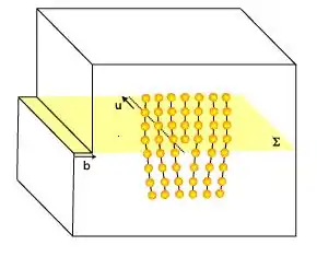
Dislocation creep takes place due to the movement of dislocations through a crystal lattice. Each time a dislocation moves through a crystal, part of the crystal shifts by one lattice point along a plane, relative to the rest of the crystal. The plane that separates the shifted and unshifted regions along which the movement takes place is the slip plane. To allow for this movement, all ionic bonds along the plane must be broken. If all bonds were broken at once, this would require so much energy that dislocation creep would only be possible in theory. When it is assumed that the movement takes place step by step, the breaking of bonds is immediately followed by the creation of new ones and the energy required is much lower. Calculations of molecular dynamics and analysis of deformed materials have shown that dislocation creep can be an important factor in deformation processes.
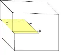
By moving a dislocation step by step through a crystal lattice, a linear lattice defect is created between parts of the crystal lattice.[3] Two types of dislocations exist: edge and screw dislocations. Edge dislocations form the edge of an extra layer of atoms inside the crystal lattice. Screw dislocations form a line along which the crystal lattice jumps one lattice point. In both cases the dislocation line forms a linear defect through the crystal lattice, but the crystal can still be perfect on all sides of the line.
The length of the displacement in the crystal caused by the movement of the dislocation is called the Burgers vector. It equals the distance between two atoms or ions in the crystal lattice. Therefore, each material has its own characteristic Burgers vectors for each glide plane.
Glide planes in crystals
Both edge and screw dislocations move (slip) in directions parallel to their Burgers vector. Edge dislocations move in directions perpendicular to their dislocation lines and screw dislocations move in directions parallel to their dislocation lines. This causes a part of the crystal to shift relative to its other parts. Meanwhile, the dislocation itself moves further on along a glide plane. The crystal system of the material (mineral or metal) determines how many glide planes are possible, and in which orientations. The orientation of the differential stress determines which glide planes are active and which are not. The Von Mises criterion states that to deform a material, movement along at least five different glide planes is required. A dislocation will not always be a straight line and can thus move along more than one glide plane. Where the orientation of the dislocation line changes, a screw dislocation can continue as an edge dislocation and vice versa.
Origin of dislocations
When a crystalline material is put under differential stress, dislocations form at the grain boundaries and begin moving through the crystal.
New dislocations can also form from Frank–Read sources. These form when a dislocation is stopped in two places. The part of the dislocation in between will move forward, causing the dislocation line to curve. This curving can continue until the dislocation curves over itself to form a circle. In the centre of the circle, the source will produce a new dislocation, and this process will produce a sequence of concentric dislocations on top of each other. Frank–Read sources are also created when screw dislocations double cross-slip (change slip planes twice), as the jogs in the dislocation line pin the dislocation in the 3rd plane.
Dislocation movement
Dislocation glide
A dislocation can ideally move through a crystal until it reaches a grain boundary (the boundary between two crystals). When it reaches a grain boundary, the dislocation will disappear. In that case the whole crystal is sheared a little (needs a reference). There are however different ways in which the movement of a dislocation can be slowed or stopped. When a dislocation moves along several different glide planes, it can have different velocities in these different planes, due to the anisotropy of some materials. Dislocations can also encounter other defects in the crystal on their ways, such as other dislocations or point defects. In such cases a part of the dislocation could slow down or even stop moving altogether.
In alloy design, this effect is used to a great extent. On adding a dissimilar atom or phase, such as a small amount of carbon to iron, it is hardened, meaning deformation of the material will be more difficult (the material becomes stronger). The carbon atoms act as interstitial particles (point defects) in the crystal lattice of the iron, and dislocations will not be able to move as easily as before.
Dislocation climb and recovery
Dislocations are imperfections in a crystal lattice, that from a thermodynamic point of view increase the amount of free energy in the system. Therefore, parts of a crystal that have more dislocations will be relatively unstable. By recrystallisation, the crystal can heal itself. Recovery of the crystal structure can also take place when two dislocations with opposite displacement meet each other.
A dislocation that has been brought to a halt by an obstacle (a point defect) can overcome the obstacle and start moving again by a process called dislocation climb. For dislocation climb to occur, vacancies have to be able to move through the crystal. When a vacancy arrives at the place where the dislocation is stuck it can cause the dislocation to climb out of its glide plane, after which the point defect is no longer in its way. Dislocation climb is therefore dependent from the velocity of vacancy diffusion. As with all diffusion processes, this is highly dependent on the temperature. At higher temperatures dislocations will more easily be able to move around obstacles. For this reason, many hardened materials become exponentially weaker at higher temperatures.
To reduce the free energy in the system, dislocations tend to concentrate themselves in low-energy regions, so other regions will be free of dislocations. This leads to the formation of 'dislocation walls', or planes in a crystal where dislocations localize. Edge dislocations form tilt walls,[4] while screw dislocations form twist walls. In both cases, the increasing localisation of dislocations in the wall will increase the angle between the orientation of the crystal lattice on both sides of the wall. This leads to the formation of subgrains. The process is called subgrain rotation (SGR) and can eventually lead to the formation of new grains when the dislocation wall becomes a new grain boundary.
Kinetics
In general, the power law for stage 2 creep is:
where is the stress exponent and is the creep activation energy, is the ideal gas constant, is temperature, and is a mechanism-dependent constant.
The exponent describes the degree of stress-dependence the creep mechanism exhibits. Diffusional creep exhibits an of 1 to 2, climb-controlled creep an of 3 to 5, and glide-controlled creep an of 5 to 7.
Dislocation glide

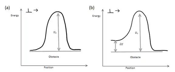
The rate of dislocation glide creep can be determined using an Arrhenius equation for the rate of dislocation motion. The forward rate can be written as:
where is the energy of the barrier and is the work provided by the applied stress and from thermal energy which helps the dislocation cross the barrier. is the Boltzmann constant and is the temperature of the system.
Similarly, the backward rate is given by:
The total creep rate is as follows:
Thus, the rate of creep due to dislocation glide is:
At low temperatures, this expression becomes:
The energy supplied to the dislocation is:
where is the applied stress, is the Burgers vector, and is the area of the slip plane. Thus, the overall expression for the rate of dislocation glide can be rewritten as:
The numerator is the energy coming from the stress and the denominator is the thermal energy.[2] This expression is derived from a model from which plastic strain does not devolve from atomic diffusion.[2]
The creep rate is defined by the intrinsic activation energy ( ) and the ratio of stress-assisted energy () to thermal energy ( ). The creep rate increases as this ratio increases, or as stress-assisted energy increases more than thermal energy. All creep rate expressions have similar terms, but the strength of the dependency (i.e. the exponent) on internal activation energy or stress-assisted energy varies with the creep mechanism.
Creep by Dislocation and Diffusional Flow
Creep mechanisms which involve both dislocation creep and diffusional creep include solute-drag creep, dislocation climb-glide creep, and Harper–Dorn creep.
Solute-Drag creep


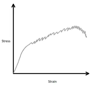
Solute-drag creep is characterized by serrated flow [2] and is typically observed in metallic alloys that do not exhibit short-time creep behavior – the creep rate of these material increases during transient creep before reaching steady-state.[2]
Similar to solid-solution strengthening, the size misfit parameter between solute atoms and dislocations results in the restriction of dislocation motion. At low temperatures, the solute atoms do not have enough energy to move. However, at higher temperatures, the solute atoms become mobile and contribute to creep.
Solute drag creep occurs when a dislocation breaks away from a solute atom, followed by the solute atom "catching up" to the dislocation. The dislocations are originally pinned into place by solute atoms. After some initial energy input, the dislocation breaks away and begins to move with velocity . This strain rate, is :
where is the dislocation density, is the burgers vector, and is the average velocity of the dislocation.
When the dislocation velocity is not too high (or the creep rate is not too high), the solute atom can follow the dislocations, and thus introduce "drag" on the dislocation motion. A high diffusivity decreases the drag, and greater misfit parameters lead to greater binding energies between the solute atom and the dislocation, resulting in an increase in drag. Lastly, increasing the solute concentration increases the drag effect. The velocity can thus be described as follows:
where is the size misfit parameter and is the concentration of solute.[2]
As stress is applied, the dislocation velocity increases until the dislocation breaks away from the solute atoms. Then, the stress begins to decrease as the dislocation is breaking away, so the dislocation velocity decreases. This permits solute atoms to catch up to the dislocation, thereby increasing the stress once more. The stress then increases, and the cycle begins again, resulting in the serrations observed in the stress–strain diagram. This phenomenon is the Portevin–Le Chatelier effect and is only observed over limited strain-rate conditions. If the strain rate is high enough, the flow stress is greater than the breakaway stress, and the dislocation continues to move and the solute atom cannot "catch up"; thus, serrated flow is not observed.
It is also known that , which implies dislocation multiplication (an increase in stress increases the dislocation density). Thus, the solute drag creep rate can be rewritten as:
where it is noted that the diffusion coefficient is a function of temperature. This expression resembles the power law for creep above, with exponent .
Dislocation climb-glide creep
Dislocation climb-glide creep is observed in materials that exhibit a higher initial creep rate than the steady-state creep rate.[2]
Dislocations glide along a slip plane until they reach an obstacle. The applied stress is not enough for the dislocation to overcome the obstacle, but it is enough for the dislocation to climb to a parallel slip plane via diffusion. This is conceptually similar to a high-temperature cross-slip, where dislocations circumvent obstacles via climb at low temperatures. The dislocation motion involves climb and glide, thus the name climb-glide creep.
The rate is determined by the slower (lower velocity) of the climb and glide processes, thus the creep rate is often determined by the climb rate.
Starting with the general strain rate form:
where is the dislocation density and is the dislocation glide velocity. The dislocation glide velocity is higher than the dislocation climb velocity, . Climb and glide are related via this expression:
- where
is the distance that dislocations glide in the slip plane and is the separation between parallel slip planes.
Considering a model in which dislocations are emitted by a source, to maintain the constant microstructure evolution from Stage I to Stage II creep, each source is associated with a constant number of dislocation loops that it has emitted. Thus, to dislocations may only continue to be emitted if some are annihilated. Annihilation is possible via climb, which results in mass transfer between sides of the loop (i.e. either removal of vacancies, resulting in the addition of atoms, or vice versa).[2]
Assuming there are dislocation sources per unit volume, the dislocation can be rewritten in terms of the average loop diameter , the climb-glide creep rate is:
As the microstructure must remain fixed for the transition between these stages, remains fixed. Thus, it can be multiplied by the volume per source and remain constant, thus . The expression for the climb-glide creep rate reduces to:
As dislocation climb is driven by stress but accomplished by diffusion, we can say where is the lattice diffusion constant. can be expressed in its normalized form, , where is the atomic volume.
Thus, the dislocation climb-glide creep rate can be expressed as follows:
where is a constant that encompasses details of the loop geometry.[2] At higher stress levels, a finer microstructure is observed, which correlates to the inverse relationship between and . If is independent of stress, which has not been shown yet, the exponent for this dislocation creep is 4.5 .[2]
Harper–Dorn creep
Harper–Dorn creep is a climb-controlled creep mechanism. At low stresses, materials with a low initial dislocation density may creep by dislocation climb alone. Harper-Dorn creep is characterized by a linear steady-state strain rate relationship with stress at constant temperature and as independent of grain size, and activation energies that are typically close to those expected for lattice diffusion.[5] The Harper-Dorn creep rate can be described as follows:
where is the creep rate, is the dislocation density, is the material diffusivity, is the shear modulus, is the burgers vector, is the Boltzmann constant, is the temperature, and is the applied stress. In Harper-Dorn creep, the dislocation density is constant.[6]
See also
Notes
- ↑ Twiss & Moores (2000), p. 396
- 1 2 3 4 5 6 7 8 9 10 11 Courtney, Thomas H. (2000). Mechanical behavior of materials (2nd ed.). Boston: McGraw Hill. ISBN 0070285942. OCLC 41932585.
- ↑ Twiss & Moores (2000), pp. 395–396
- ↑ Poirier (1976)
- ↑ Kumar, Praveen, Michael E. Kassner, and Terence G. Langdon. "Fifty years of Harper–Dorn creep: a viable creep mechanism or a Californian artifact?." Journal of materials science 42.2 (2007): 409–420.
- ↑ Mohamed, F. A.; Murty, K. L.; Morris, J. W. (1973-04-01). "Harper-dorn creep in al, pb, and sn". Metallurgical Transactions. 4 (4): 935–940. Bibcode:1973MT......4..935M. doi:10.1007/BF02645593. ISSN 1543-1916. S2CID 137369205.
Literature
- Poirier, J.P.; 1976: Plasticité à haute température des solides cristallins, Eyrolles, Paris.
- Twiss, R.J. & Moores, E.M., 2000: Structural Geology, W.H. Freeman & co (6th ed.), ISBN 0-7167-2252-6