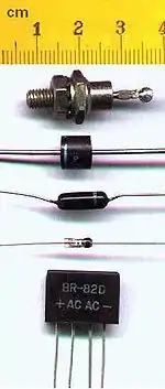
Diodes are the basic building blocks for most semiconductor devices. They are part of the bipolar family of devices. Diodes consist of two semiconductor materials, one doped with a deficiency of electrons called p-type material, and the other side is doped with an extra abundancy of electrons called n-type material. A process known as doping the material is what makes some parts of the diode p-type and the other parts n-type.
While growing the semiconductor crystal, a small amount of arsenic or phosporous can be mixed in with the process and dope the material. To change the type of material from p to n type, one can add some n-type chemicals to swamp out the p-type materials already in the 'substrate'. When you get done with the making of a diode, you have two types of material in direct contact with one another - this is called an abrupt pn-junction. The p-side is called the anode and collects the electrons emitted from the cathode, the n-side.
Diode's construction
Diode is made from joining one P-typed semi conductor with one N-typed semi conductor . A bipolar device of distinct polarties . Positive at the end of P-typed semi conductor and negative at the end of N-typed semi conductor . A device directs the flow of current , in the direction of the arrow pointing
- + o--[P|N]--o -
Diode's Symbol
Diode's current and voltage curve
Diode's current and voltage curve or I V Curve shows manufacturer's specification of diode's operation voltage and current
As seen in the graph above the diode actually works in both the forward region and the backward region. In the forward region the value of I and V are positive and in the backward region I and V are negative.
Diode's Operation
Forward Region
Region where current and voltage are positive
- When . . Diode does not conduct (Diode is switch OFF)
- When . . Diode starts to conduct (Diode is switch ON)
- When . Diode conducts current and current is calculated by
With
- is called Forward Break Over Voltage
Backward Region
- Current and Voltage are Negative . When the value of voltage is more negative than the Peak Inverse Voltage (PIV) Voltage the Diode will be destroyed
In summary
There are three modes in which a diode operates:
- Forward . No current flows until a small forward voltage is reached called cut-in voltage.
- Reverse . The diode prevents current from flowing in the opposite direction. Current is small, and voltage can be large (but not exceeding the Zener voltage.)
- Breakdown . Once the diode voltage is more negative than the Zener voltage, the diode allows current to flow in the reverse direction.
When there is no voltage applied, the excess electrons of the N type semiconductor flow into the holes of the P type semiconductor. This creates a depletion region that acts as a voltage.
Ideal Diode
The real diode approaches the ideal diode in the sense that the reverse current is extremely small (less than 1fA) at least for a significant part of the characteristic, and the forward current is very high (on the order of 1mA). Although a real diode does not have the characteristics as the ideal diode, in theory it is possible to make an ideal diode if the concentrations of dopants in both the regions are infinite. However, there is no way of actually doing this and experiments do not agree.
The Shockley equation
The diode reverse (saturation) current is governed by the doping concentration. The current flowing through the device varies as the voltage applied across it changes as given by the Shockley diode equation (not to be confused with Schottky):
is defined as , where is Boltzmann's constant, is the temperature in Kelvin, and is the magnitude of the charge on an electron.
In the forward bias direction, current flows with low voltage. If one draws a characteristic for this equation, a sharp increase in current can be seen at a particular voltage called the cut-in voltage or the on-voltage.
In the reverse bias mode, the diode current is approximately . This is called the reverse saturation current because it looks like the diode is saturated with charge and cannot allow more current in the reverse bias direction than this.
Diode's Break-down
However, a break from the above equation takes place at a point called break-down voltage. One could think of it as the point where the Shockley equation breaks down and is no longer valid. There are two reasons for breakdown to occur.
Avalanche Breakdown
- This occurs as a result of excess minority carriers in a region. Minority carriers are those carriers that are in the wrong region. For example, electrons will be minority carriers in the p-region.
Zener Breakdown
- This is basically due to a size difference or dopant concentration difference. One of the regions has a greater region of depletion (Reverse bias voltage induces a depletion region, which is sparse in a densely doped region and dense in a sparsely doped region. )
Diode Types
LED (Light Emitting Diode) 
Schottky diode 
Zener diode 
Varicap diode
Diode's Circuits
DC Circuit
AC Circuit
Rectifier Depend on connection of AC voltage sinusoidal wave with diode , diodes will pass only positive or negative 1/2 cycle of sinusoidal voltage wave
- AC full wave --|>|-- Positive portion of the wave
- AC full wave --|<|-- Nagative portion of the wave
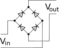
Bridge Rectifier:

- A diode circuit that 'rectifies' alternating current (AC) into direct current (DC). The bridge rectifier is a full-wave rectifier, meaning that both the positive and negative portions of the wave become positive. (In a half-wave rectifier, positive stays positive, and negative becomes zero.) The bridge rectifier has advantages over other full-wave rectifier designs, because it reduces peak-inverse voltage (PIV), the largest negative voltage across a single junction diode. By reducing the PIV, it becomes possible to use diodes with lower breakdown (Zener) voltages. This allows the use of cheaper diodes to perform the same function.
Reference
External Links
- Rectification Basics: Electronics for Beginners
