Wikiversity Electrical Engineering School The Lessons in ELECTRIC CIRCUITS ANALYSIS COURSE |
Lesson Review 5:What you need to remember from Kirchhoff's Voltage Law. If you ever feel lost, do not be shy to go back to the previous lesson & go through it again. You can learn by repitition.
Lesson 6: PreviewThis Lesson is about Kirchhoff's Current Law. The student/User is expected to understand the following at the end of the lesson.
|
| ||||||||||||||||||||||||||||||||||||||||||||||
Part 1: Kirchhoff's Current LawKirchhoff's Current Law states:
We can now define the electrical point physically connecting two or more electric circuit components, as a NODE. Note that a positive current leaving a point is considered to be a negative current entering that point. Mathematically, Kirchhoff's Current Law is given by For reference, this law is sometimes called Kirchhoff's first law, Kirchhoff's point rule, Kirchhoff's junction rule, and Kirchhoff's first rule. |
Part 2:Kirchhoff's Current Law (Cont...)
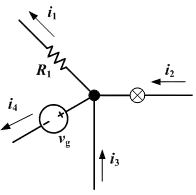
We observe four currents "entering" the junction depicted as the bold black dot in Figure 6.1. Of course, two currents are actually exiting the junction , but for the purposes of circuit analysis it is generally less restrictive to consider what are in actuality positive currents flowing out of a junction to be negative currents flowing into that junction (mathematically the same thing). Doing so allows us to write Kirchhoff's law for this example as: |
Part 3It may not be clear at this point why we insist on thinking of negative currents flowing into a junction instead of positive currents flowing out. But note that Figure 6.1 provides us with more information that we generally can expect to get when analysing circuits, namely the helpful arrows indicating the direction of current flow. If we don't have such assistance, we generally should not pass judgment on the direction of current flow (i.e., placing a negative sign before our current variable) until we calculate it, lest we confuse ourselves and make mistakes. Nevertheless in this case we have the extra information of directional arrows in Figure 6.1, so we should take advantage of it. We know that currents i2 and i3 flow into the junction and the currents i1 and i4 flow out. Thus we can write Kirchhoff's Current Law as written is only applicable to steady-state current flow (i.e., no alternating current, no signal transmission). It can be extended to include time-dependent current flow, but that is beyond the scope of this section. Kirchhoff's Current Law is used in a method of circuit analysis referred to as nodal analysis to be discussed in Lecture 7. A node is a section of a circuit where there is no change in voltage (where there are no components, wire is often assumed to be perfectly conductive). Each node is used to form an equation, and the equations are then solved simultaneously, giving the voltages at each node. |
Part 4 : Example
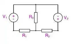
Consider Figure 6.2 with the following Parameters: Find current through using Kirchhoff's Current Law.
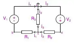
This is the same example we solved in Exercise 5. Figure 6.3 shows Voltages at Nodes a, b, c and d. We use node a as common node ( ground if you like ). thus . |
Part 5 : Example (Continued)From Node b we get: From Node d we get: It is clear that we must solve Vc, in order to complete Voltage definitions at all nodes. Vc will be found by applying KCL at node c and solving the resulting equations as follows:
and
|
Part 6 : Example (Continued)Substitute values into previous equations you get: thus Thus now we can calculate Current through as follows:
Just as we expected! Note that the current here is simplified because we were following voltage definitions and current paths in Figure 6.3. This method becomes tedious as the complexity of the circuit is increased. |
Part 7:Further Reading Links: References:
Exercise 6
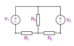
Consider Figure 6.4 with the following Parameters: Find current through using Kirchhoff's Current Law. |
Part 8: Completion List Once you finish your Exercises you can post your score here!
To post your score just e-mail your course co-ordinator your name and score *Click Here
|


