Part of:
- Engineering and Technology
- Mechanical Engineering; Production and Design Engineering
- Computer Aided Design Course
Introduction
In the previous lesson you created very simple 2D CAD models using widely available standards and tools. Several years ago, you would have spent a lot of time to achieve this. You would have had to design the database structure, object model, many algorithms and methods for input, output, transformations, visualizations and so on.
Today, advanced CAD models are built similar to our 2D example. Software engineers use available building blocks and standards to create CAD technologies with new, specialized tools and improved functionality.
3D modeling kernel
The majority of CAD software is not programed from scratch, rather it is built upon existing generic 3D modeling kernels. Usually kernels are available in the form of C libraries. Many have been developed by major software companies as a part of their CAD program and later licensed to other developers and companies.
Major kernels are:
- ACIS from Spatial (since 2000 Dassault Systèmes subsidiary)
- Parasolid from UGS
- Granite from PTC
- Open CASCADE
The best choice from a university perspective is Open CASCADE which is an open source program. You may use it freely to create your own project; you can study the code and even make improvements.
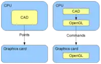
CAD software designers also use OpenGL and other standards to improve CAD functionality and performance.

OpenGL significantly improves the quality and speed of 3D model visualization, allowing the separate Graphics Processing Unit (GPU) to handle graphics rendering and freeing up Central Processing Unit (CPU) capacity, which improves CAD performance and usability. OpenGL interface offers many ready to use functions that speed up CAD development. OpenGL is supported by OS (operating system) such as Windows or Unix. CAD so first call OS function, which is performed by OS or propagated to GPU using driver. Functions and complex calculation are so preferably done by fast and optimized GPU or, if required function is not supported by graphics card GPU, then software emulation is used and calculation is done by CPU. Modern graphic cards are in fact powerful computers that process commands. That is why they are expensive and power hungry. You should be aware of GPU role while it can dramatically improve CAD performance. When using particular CAD, graphics card features (especially supported standards) should be in concordance.
Example of OpenGL code, line from 0,0 to 100,100 coordinates:
glBegin(GL_LINES);
 glVertex2f (0.0,0.0);
 glVertex2f (100.0,100.0);
glEnd();
Similarly to OpenGL HPGL (Hewlett-Packard Graphics Language) improves the performance and quality of plotting, as well software development time. Drawing is delivered to plotter or printer not as a matrix of points calculated by CPU, but as a stream of HPGL commands. Usually plotter stores data on internal hard disk and then prints drawing off line, independently on computer. Plotter or printer processor than calculates printed points (in the case of inkjet plotters and printers or pen moves in the case of older pen plotters). HPGL is part of PCL (Printer Command Language) specification.
You will need:
- Internet access and a browser