19. Stresses Permitted.—For a long time engineers held the convenient opinion that, if the total dead and live load stress on any section of a structure (of iron) did not exceed 5 tons per sq. in., ample safety was secured. It is no longer possible to design by so simple a rule. In an interesting address to the British Association in 1885, Sir B. Baker described the condition of opinion as to the safe limits of stress as chaotic. “The old foundations,” he said, “are shaken, and engineers have not come to an agreement respecting the rebuilding of the structure. The variance in the strength of existing bridges is such as to be apparent to the educated eye without any calculation. In the present day engineers are in accord as to the principles of estimating the magnitude of the stresses on the members of a structure, but not so in proportioning the members to resist those stresses. The practical result is that a bridge which would be passed by the English Board of Trade would require to be strengthened 5% in some parts and 60% in others, before it would be accepted by the German government, or by any of the leading railway companies in America.” Sir B. Baker then described the results of experiments on repetition of stress, and added that “hundreds of existing bridges which carry twenty trains a day with perfect safety would break down quickly under twenty trains an hour. This fact was forced on my attention nearly twenty-five years ago by the fracture of a number of girders of ordinary strength under a five-minutes’ train service.”
Practical experience taught engineers that though 5 tons per sq. in. for iron, or 612 tons per sq. in. for steel, was safe or more than safe for long bridges with large ratio of dead to live load, it was not safe for short ones in which the stresses are mainly due to live load, the weight of the bridge being small. The experiments of A. Wöhler, repeated by Johann Bauschinger, Sir B. Baker and others, show that the breaking stress of a bar is not a fixed quantity, but depends on the range of variation of stress to which it is subjected, if that variation is repeated a very large number of times. Let K be the breaking strength of a bar per unit of section, when it is loaded once gradually to breaking. This may be termed the statical breaking strength. Let kmax. be the breaking strength of the same bar when subjected to stresses varying from kmax. to kmin. alternately and repeated an indefinitely great number of times; kmin. is to be reckoned + if of the same kind as kmax. and − if of the opposite kind (tension or thrust). The range of stress is therefore kmax.−kmin., if the stresses are both of the same kind, and kmax.+kmin., if they are of opposite kinds. Let Δ = kmax. ± kmin. = the range of stress, where Δ is always positive. Then Wöhler’s results agree closely with the rule,
kmax. = 12Δ+√(K2−nΔK),
where n is a constant which varies from 1.3 to 2 in various qualities of iron and steel. For ductile iron or mild steel it may be taken as 1.5. For a statical load, range of stress nil, Δ = 0, kmax. = K, the statical breaking stress. For a bar so placed that it is alternately loaded and the load removed, Δ = kmax. and kmax. = 0.6 K. For a bar subjected to alternate tension and compression of equal amount, Δ = 2 fmax. and kmax. = 0.33 K. The safe working stress in these different cases is kmax. divided by the factor of safety. It is sometimes said that a bar is “fatigued” by repeated straining. The real nature of the action is not well understood, but the word fatigue may be used, if it is not considered to imply more than that the breaking stress under repetition of loading diminishes as the range of variation increases.
It was pointed out as early as 1869 (Unwin, Wrought Iron Bridges and Roofs) that a rational method of fixing the working stress, so far as knowledge went at that time, would be to make it depend on the ratio of live to dead load, and in such a way that the factor of safety for the live load stresses was double that for the dead load stresses. Let A be the dead load and B the live load, producing stress in a bar; ρ = B/A the ratio of live to dead load; f1 the safe working limit of stress for a bar subjected to a dead load only and f the safe working stress in any other case. Then
f1 (A+B)/(A+2B) = f1(1+ρ)/(1+2ρ).
The following table gives values of f so computed on the assumption that f1 = 712 tons per sq. in. for iron and 9 tons per sq. in. for steel.
| Ratio ρ |
1+ρ1+2ρ | Values of f, tons per sq. in. | ||
| Iron. | Mild Steel. | |||
| All dead load | 0 | 1.00 | 7.5 | 9.0 |
| .25 | 0.83 | 6.2 | 7.5 | |
| .33 | 0.78 | 5.8 | 7.0 | |
| .50 | 0.75 | 5.6 | 6.8 | |
| .66 | 0.71 | 5.3 | 6.4 | |
| Live load = Dead load | 1.00 | 0.66 | 4.9 | 5.9 |
| 2.00 | 0.60 | 4.5 | 5.4 | |
| 4.00 | 0.56 | 4.2 | 5.0 | |
| All live load | ∞ | 0.50 | 3.7 | 4.5 |
Bridge sections designed by this rule differ little from those designed by formulae based directly on Wöhler’s experiments. This rule has been revived in America, and appears to be increasingly relied on in bridge-designing. (See Trans. Am. Soc. C.E. xli. p. 156.)
The method of J. J. Weyrauch and W. Launhardt, based on an empirical expression for Wöhler’s law, has been much used in bridge designing (see Proc. Inst. C.E. lxiii. p. 275). Let t be the statical breaking strength of a bar, loaded once gradually up to fracture (t = breaking load divided by original area of section); u the breaking strength of a bar loaded and unloaded an indefinitely great number of times, the stress varying from u to 0 alternately (this is termed the primitive strength); and, lastly, let s be the breaking strength of a bar subjected to an indefinitely great number of repetitions of stresses equal and opposite in sign (tension and thrust), so that the stress ranges alternately from s to −s. This is termed the vibration strength. Wöhler’s and Bauschinger’s experiments give values of t, u, and s, for some materials. If a bar is subjected to alternations of stress having the range Δ = fmax.−fmin., then, by Wöhler’s law, the bar will ultimately break, if
| fmax. = FΔ, . . . | (1) |
where F is some unknown function. Launhardt found that, for stresses always of the same kind, F = (t−u)/(t−fmax.) approximately agreed with experiment. For stresses of different kinds Weyrauch found F = (u−s)/(2u−s−fmax.) to be similarly approximate. Now let fmax./fmin. = φ, where φ is + or − according as the stresses are of the same or opposite signs. Putting the values of F in (1) and solving for fmax., we get for the breaking stress of a bar subjected to repetition of varying stress,
fmax. = u(1+(t −u)φ/u) [Stresses of same sign.]
fmax. = u(1+(u−s)φ/u) [Stresses of opposite sign.]
The working stress in any case is fmax. divided by a factor of safety. Let that factor be 3. Then Wöhler’s results for iron and Bauschinger’s for steel give the following equations for tension or thrust:—
Iron, working stress, f = 4.4 (1+12φ)
Steel, working stress, f = 5.87 (1+12φ).
In these equations φ is to have its + or − value according to the case considered. For shearing stresses the working stress may have 0.8 of its value for tension. The following table gives values of the working stress calculated by these equations:—
| φ | 1+ φ2 | Working Stress f, tons per sq. in. | ||
| Iron. | Steel. | |||
| All dead load | 1.0 | 1.5 | 6.60 | 8.80 |
| 0.75 | 1.375 | 6.05 | 8.07 | |
| 0.50 | 1.25 | 5.50 | 7.34 | |
| 0.25 | 1.125 | 4.95 | 6.60 | |
| All live load | 0.00 | 1.00 | 4.40 | 5.87 |
| −0.25 | 0.875 | 3.85 | 5.14 | |
| −0.50 | 0.75 | 3.30 | 4.40 | |
| −0.75 | 0.625 | 2.75 | 3.67 | |
| Equal stresses + and − | −1.00 | 0.500 | 2.20 | 2.93 |
To compare this with the previous table, φ = (A+B)/A = 1+ρ. Except when the limiting stresses are of opposite sign, the two tables agree very well. In bridge work this occurs only in some of the bracing bars.
It is a matter of discussion whether, if fatigue is allowed for by the Weyrauch method, an additional allowance should be made for impact. There was no impact in Wöhler’s experiments, and therefore it would seem rational to add the impact allowance to that for fatigue; but in that case the bridge sections become larger than experience shows to be necessary. Some engineers escape this difficulty by asserting that Wöhler’s results are not applicable to bridge work. They reject the allowance for fatigue (that is, the effect of repetition) and design bridge members for the total dead and live load, plus a large allowance for impact varied according to some purely empirical rule. (See Waddell, De Pontibus, p.7.) Now in applying Wöhler’s law, fmax. for any bridge member is found for the maximum possible live load, a live load which though it may sometimes come on the bridge and must therefore be provided for, is not the usual live load to which the bridge is subjected. Hence the range of stress, fmax.−fmin., from which the working stress is deduced, is not the ordinary range of stress which is repeated a practically infinite number of times, but is a range of stress to which the bridge is subjected only at comparatively long intervals. Hence practically it appears probable that the allowance for fatigue made in either of the tables above is sufficient to cover the ordinary effects of impact also.
English bridge-builders are somewhat hampered in adopting rational limits of working stress by the rules of the Board of Trade. Nor do they all accept the guidance of Wöhler’s law. The following are some examples of limits adopted. For the Dufferin bridge (steel) the working stress was taken at 6.5 tons per sq. in. in bottom booms and diagonals, 6.0 tons in top booms, 5.0 tons in verticals and long compression members. For the Stanley bridge at Brisbane the limits were 6.5 tons per sq. in. in compression boom, 7.0 tons in tension boom, 5.0 tons in vertical struts, 6.5 tons in diagonal ties, 8.0 tons in wind bracing, and 6.5 tons in cross and rail girders. In the new Tay bridge the limit of stress is generally 5 tons per sq. in., but in members in which the stress changes sign 4 tons per sq. in. In the Forth bridge for members in which the stress varied from 0 to a maximum frequently, the limit was 5.0 tons per sq. in., or if the stress varied rarely 5.6 tons per sq. in.; for members subjected to alternations of tension and thrust frequently 3.3 tons per sq. in. or 5 tons per sq. in. if the alternations were infrequent. The shearing area of rivets in tension members was made 112 times the useful section of plate in tension. For compression members the shearing area of rivets in butt-joints was made half the useful section of plate in compression.

|
| Fig. 37. |
20. Determination of Stresses in the Members of Bridges.—It is convenient to consider beam girder or truss bridges, and it is the stresses in the main girders which primarily require to be determined. A main girder consists of an upper and lower flange, boom or chord and a vertical web. The loading forces to be considered are vertical, the horizontal forces due to wind pressure are treated separately and provided for by a horizontal system of bracing. For practical purposes it is accurate enough to consider the booms or chords as carrying exclusively the horizontal tension and compression and the web as resisting the whole of the vertical and, in a plate web, the equal horizontal shearing forces. Let fig. 37 represent a beam with any system of loads W1, W2, . . . Wn.
The reaction at the right abutment is
R2 = W1x1/l+W2x2/l+. . .
That at the left abutment is
R1 = W1+W2+ . . .−R2.
Consider any section a b. The total shear at a b is
S = R–Σ(W1+W2 . . .)
where the summation extends to all the loads to the left of the section. Let p1, p2 . . . be the distances of the loads from a b, and p the distance of R1 from a b; then the bending moment at a b is
M = R1p−Σ(W1p1+W2p2 . . .)
where the summation extends to all the loads to the left of a b. If the loads on the right of the section are considered the expressions are similar and give the same results.
If At Ac are the cross sections of the tension and compression flanges or chords, and h the distance between their mass centres, then on the assumption that they resist all the direct horizontal forces the total stress on each flange is
Ht = Hc = M/h
and the intensity of stress of tension or compression is
ft = M/At h,
fc = M/Ach.
If A is the area of the plate web in a vertical section, the intensity of shearing stress is
fx = S/A
and the intensity on horizontal sections is the same. If the web is a braced web, then the vertical component of the stress in the web bars cut by the section must be equal to S.
|
| Fig. 38. |
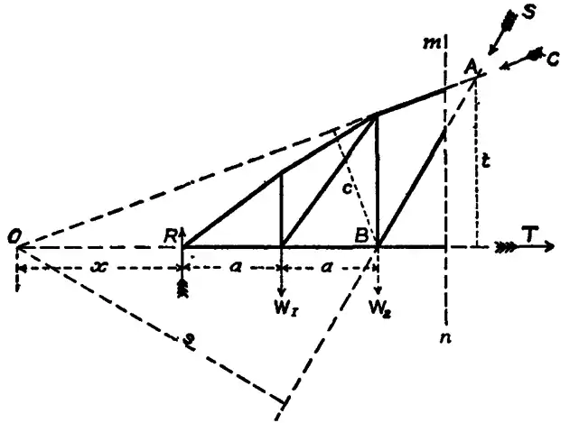
21. Method of Sections. A. Ritter’s Method.—In the case of braced structures the following method is convenient: When a section of a girder can be taken cutting only three bars, the stresses in the bars can be found by taking moments. In fig. 38 m n cuts three bars, and the forces in the three bars cut by the section are C, S and T. There are to the left of the section the external forces, R, W1, W2. Let s be the perpendicular from O, the join of C and T on the direction of S; t the perpendicular from A, the join of C and S on the direction of T; and c the perpendicular from B, the join of S and T on the direction of C. Taking moments about O,
Rx−W1(x+a)−W2(x+2a) = Ss;
taking moments about A,
R3a−W12a−W2a = Tt;
and taking moments about B,
R2a−W1a = Cc
Or generally, if M1 M2 M3 are the moments of the external forces to the left of O, A, and B respectively, and s, t and c the perpendiculars from O, A and B on the directions of the forces cut by the section, then
Ss = M1; Tt = M2 and Cc = M3.
Still more generally if H is the stress on any bar, h the perpendicular distance from the join of the other two bars cut by the section, and M is the moment of the forces on one side of that join,
Hh = M.
 |
|
| Fig. 39. | Fig. 40. |
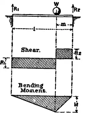
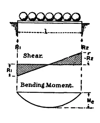
22. Distribution of Bending Moment and Shearing Force.—Let a girder of span l, fig. 39, supported at the ends, carry a fixed load W at m from the right abutment. The reactions at the abutments are R1 = Wm/l and R2 = W(l−m)/l. The shears on vertical sections to the left and right of the load are R1 and −R2, and the distribution of shearing force is given by two rectangles. Bending moment increases uniformly from either abutment to the load, at which the bending moment is M = R2m = R1(l−m). The distribution of bending moment is given by the ordinates of a triangle. Next let the girder carry a uniform load w per ft. run (fig. 40). The total load is wl; the reactions at abutments, R1 = R2 = 12wl. The distribution of shear on vertical sections is given by the ordinates of a sloping line. The greatest bending moment is at the centre and = Mc = 18wl2. At any point x from the abutment, the bending moment is M = 12wx(l−x), an equation to a parabola.
|
| Fig. 41. |
|
| Fig. 42. |
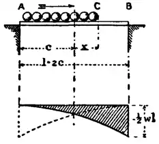
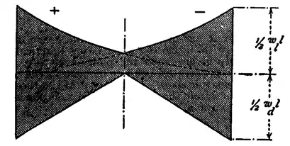
23. Shear due to Travelling Loads.—Let a uniform train weighing w per ft. run advance over a girder of span 2c, from the left abutment. When it covers the girder to a distance x from the centre (fig. 41) the total load is w(c+x); the reaction at B is
R2 = w(c+x) ✕ (c+x)4c = w4c(c+x)2,
which is also the shearing force at C for that position of the load. As the load travels, the shear at the head of the train will be given by the ordinates of a parabola having its vertex at A, and a maximum Fmax. = −12wl at B. If the load travels the reverse way, the shearing force at the head of the train is given by the ordinates of the dotted parabola. The greatest shear at C for any position of the load occurs when the head of the train is at C. For any load p between C and B will increase the reaction at B and therefore the shear at C by part of p, but at the same time will diminish the shear at C by the whole of p. The web of a girder must resist the maximum shear, and, with a travelling load like a railway train, this is greater for partial than for complete loading. Generally a girder supports both a dead and a live load. The distribution of total shear, due to a dead load wl per ft. run and a travelling load wl per ft. run, is shown in fig. 42, arranged so that the dead load shear is added to the maximum travelling load shear of the same sign.
|
| Fig. 43. |
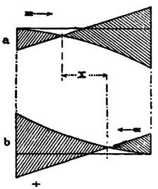
24. Counterbracing.—In the case of girders with braced webs, the tension bars of which are not adapted to resist a thrust, another circumstance due to the position of the live load must be considered. For a train advancing from the left, the travelling load shear in the left half of the span is of a different sign from that due to the dead load. Fig. 43 shows the maximum shear at vertical sections due to a dead and travelling load, the latter advancing (fig. 43, a) from the left and (fig. 43, b) from the right abutment. Comparing the figures it will be seen that over a distance x near the middle of the girder the shear changes sign, according as the load advances from the left or the right. The bracing bars, therefore, for this part of the girder must be adapted to resist either tension or thrust. Further, the range of stress to which they are subjected is the sum of the stresses due to the load advancing from the left or the right.
 |
|
| Fig. 44. | Fig. 45. |

| |
| Fig. 46. | |
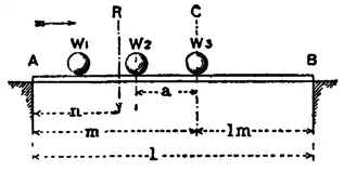
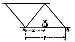
25. Greatest Shear when concentrated Loads travel over the Bridge.—To find the greatest shear with a set of concentrated loads at fixed distances, let the loads advance from the left abutment, and let C be the section at which the shear is required (fig. 44). The greatest shear at C may occur with W1 at C. If W1 passes beyond C, the shear at C will probably be greatest when W2 is at C. Let R be the resultant of the loads on the bridge when W1 is at C. Then the reaction at B and shear at C is Rn/l. Next let the loads advance a distance a so that W2 comes to C. Then the shear at C is R(n+a)/l−W1, plus any reaction d at B, due to any additional load which has come on the girder during the movement. The shear will therefore be increased by bringing W2 to C, if Ra/l+d > W1 and d is generally small and negligible. This result is modified if the action of the load near the section is distributed to the bracing intersections by rail and cross girders. In fig. 45 the action of W is distributed to A and B by the flooring. Then the loads at A and B are W(p−x)/p and Wx/p. Now let C (fig. 46) be the section at which the greatest shear is required, and let the loads advance from the left till W1 is at C. If R is the resultant of the loads then on the girder, the reaction at B and shear at C is Rn/l. But the shear may be greater when W2 is at C. In that case the shear at C becomes R(n+a)/l+d−W1, if a > p, and R(n+a)/l+d−W1a/p, if a < p. If we neglect d, then the shear increases by moving W2 to C, if Ra/l > W1 in the first case, and if Ra/l > W1a/p in the second case.
|
| Fig. 47. |
|
| Fig. 48. |
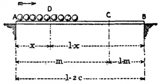
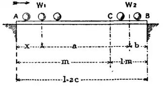
26. Greatest Bending Moment due to travelling concentrated Loads.—For the greatest bending moment due to a travelling live load, let a load of w per ft. run advance from the left abutment (fig. 47), and let its centre be at x from the left abutment. The reaction at B is 2wx2/l and the bending moment at any section C, at m from the left abutment, is 2wx2/(l−m)/l, which increases as x increases till the span is covered. Hence, for uniform travelling loads, the bending moments are greatest when the loading is complete. In that case the loads on either side of C are proportional to m and l-m. In the case of a series of travelling loads at fixed distances apart passing over the girder from the left, let W1, W2 (fig. 48), at distances x and x+a from the left abutment, be their resultants on either side of C. Then the reaction at B is W1x/l+W2(x+a)/l. The bending moment at C is
M = W1x(l−m)/l+W2m{1−(x+a)/l}.
If the loads are moved a distance ∆x to the right, the bending moment becomes
M+∆M = W1(x+∆x)(l−m)/l+W2m{1−(x+∆x+a)/l}
∆m = W1∆x(l−m)/l−W2∆xm/l,
and this is positive or the bending moment increases, if W1(l−m) > W2m, or if W1/m > W2/(l−m). But these are the average loads per ft. run to the left and right of C. Hence, if the average load to the left of a section is greater than that to the right, the bending moment at the section will be increased by moving the loads to the right, and vice versa. Hence the maximum bending moment at C for a series of travelling loads will occur when the average load is the same on either side of C. If one of the loads is at C, spread over a very small distance in the neighbourhood of C, then a very small displacement of the loads will permit the fulfilment of the condition. Hence the criterion for the position of the loads which makes the moment at C greatest is this: one load must be at C, and the other loads must be distributed, so that the average loads per ft. on either side of C (the load at C being neglected) are nearly equal. If the loads are very unequal in magnitude or distance this condition may be satisfied for more than one position of the loads, but it is not difficult to ascertain which position gives the maximum moment. Generally one of the largest of the loads must be at C with as many others to right and left as is consistent with that condition.
This criterion may be stated in another way. The greatest bending moment will occur with one of the greatest loads at the section, and when this further condition is satisfied. Let fig. 49 represent a beam with the series of loads travelling from the right. Let a b be the section considered, and let Wx be the load at a b when the bending moment there is greatest, and Wn the last load to the right then on the bridge. Then the position of the loads must be that which satisfies the condition
xl greater than W1+W2+. . . Wx−1W1+W2+. . . Wn
xl less than W1+W2+. . . WxW1+W2+. . . Wn
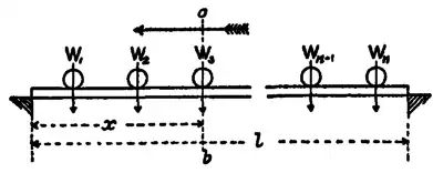
Fig. 49.
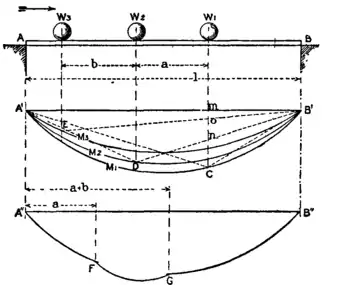
Fig. 50.
Fig. 50 shows the curve of bending moment under one of a series of travelling loads at fixed distances. Let W1, W2, W3 traverse the girder from the left at fixed distances a, b. For the position shown the distribution of bending moment due to W1 is given by ordinates of the triangle A′CB′; that due to W2 by ordinates of A′DB′; and that due to W3 by ordinates A′EB′. The total moment at W1, due to three loads, is the sum mC+mn+mo of the intercepts which the triangle sides cut off from the vertical under W1. As the loads move over the girder, the points C, D, E describe the parabolas M1, M2, M3, the middle ordinates of which are 14W1l, 14W2l, and 14W3l. If these are first drawn it is easy, for any position of the loads, to draw the lines B′C, B′D, B′E, and to find the sum of the intercepts which is the total bending moment under a load. The lower portion of the figure is the curve of bending moments under the leading load. Till W1 has advanced a distance a only one load is on the girder, and the curve A″F gives bending moments due to W1 only; as W1 advances to a distance a+b, two loads are on the girder, and the curve FG gives moments due to W1 and W2. GB″ is the curve of moments for all three loads W1+W2+W3.
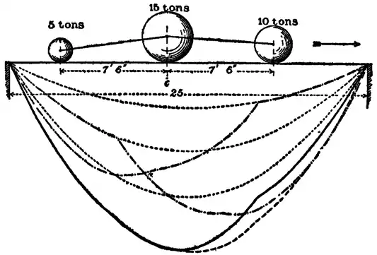
Fig. 51.
Fig. 51 shows maximum bending moment curves for an extreme case of a short bridge with very unequal loads. The three lightly dotted parabolas are the curves of maximum moment for each of the loads taken separately. The three heavily dotted curves are curves of maximum moment under each of the loads, for the three loads passing over the bridge, at the given distances, from left to right. As might be expected, the moments are greatest in this case at the sections under the 15-ton load. The heavy continuous line gives the last-mentioned curve for the reverse direction of passage of the loads.
With short bridges it is best to draw the curve of maximum bending moments for some assumed typical set of loads in the way just described, and to design the girder accordingly. For longer bridges the funicular polygon affords a method of determining maximum bending moments which is perhaps more convenient. But very great accuracy in drawing this curve is unnecessary, because the rolling stock of railways varies so much that the precise magnitude and distribution of the loads which will pass over a bridge cannot be known. All that can be done is to assume a set of loads likely to produce somewhat severer straining than any probable actual rolling loads. Now, except for very short bridges and very unequal loads, a parabola can be found which includes the curve of maximum moments. This parabola is the curve of maximum moments for a travelling load uniform per ft. run. Let we be the load per ft. run which would produce the maximum moments represented by this parabola. Then we may be termed the uniform load per ft. equivalent to any assumed set of concentrated loads. Waddell has calculated tables of such equivalent uniform loads. But it is not difficult to find we, approximately enough for practical purposes, very simply. Experience shows that (a) a parabola having the same ordinate at the centre of the span, or (b) a parabola having the same ordinate at one-quarter span as the curve of maximum moments, agrees with it closely enough for practical designing. A criterion already given shows the position of any set of loads which will produce the greatest bending moment at the centre of the bridge, or at one-quarter span. Let Mc and Ma be those moments. At a section distant x from the centre of a girder of span 2c, the bending moment due to a uniform load we per ft. run is
M = 12we(c−x)(c+x).
Putting x = 0, for the centre section
Mc = 12wec2;
and putting x = 12c, for section at quarter span
Ma = 38wec2.
From these equations a value of we can be obtained. Then the bridge is designed, so far as the direct stresses are concerned, for bending moments due to a uniform dead load and the uniform equivalent load we.