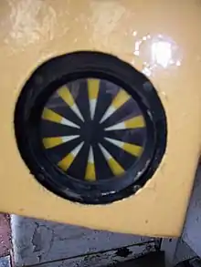
Automatic Warning System (AWS) is a railway safety system invented and predominantly used in the United Kingdom. It provides a train driver with an audible indication of whether the next signal they are approaching is clear or at caution.[1] Depending on the upcoming signal state, the AWS will either produce a 'horn' sound (as a warning indication), or a 'bell' sound (as a clear indication). If the train driver fails to acknowledge a warning indication, an emergency brake application is initiated by the AWS. However if the driver correctly acknowledges the warning indication by pressing an acknowledgement button, then a visual 'sunflower' is displayed to the driver, as a reminder of the warning.
Principles of operation
AWS is a system based on trains detecting magnetic fields. These magnetic fields are created by permanent magnets and electromagnets installed on the track. The polarity and sequence of magnetic fields detected by a train determine the type of indication given to the train driver.
A magnet, known as an AWS magnet is installed on the track center line. The magnetic field of the magnet is set based on the next signal aspect.[1] The train detects the polarity of magnetic field via an AWS receiver, permanently mounted under the train.[1]
An AWS magnet is made up of 1 permanent magnet, and an optional electromagnet. The permanent magnet is uncontrollable, and always produces a constant magnetic field of unchanging polarity. A train running over the permanent magnet will deliver an AWS warning indication to the train driver.
The optional electromagnet can be used to provide the train driver with an AWS clear indication. If the train AWS detects a second magnetic field of a certain polarity after the first permanent magnet, then the AWS displays a clear indication instead of a warning indication. The train detects the electromagnet polarity after the permanent magnet polarity. This is because the optional electromagnet is always installed after the permanent magnet (in the direction of travel). The electromagnet is connected to the green signal aspect, so the driver will only receive an AWS clear indication if the signal is clear (green).
The permanent magnet always produces a south pole. If the electromagnet is energized to produce a north pole, the AWS will give the driver an AWS clear indication.
Multiple unit trains have an AWS receiver at each end. Vehicles that can operate singly (single car DMUs and locomotives) only have one; this could be either at the front or rear depending on the direction the vehicle is traveling in.
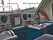
The equipment on a train consists of;
- An AWS receiver (a magnetic field detector located under the driving cab of the train)
- An AWS visual indicator (known as the 'sunflower')
- An AWS audible indicator (capable of producing two different sounds, clear indication sound = bell, warning indication sound = 'horn', or electronic equivalents)
- An AWS Acknowledge button (used to acknowledge the audible AWS warning indication. If not pressed within 2-3 seconds of an AWS warning indication, emergency brakes are applied) [1]
- An AWS isolation/fault indicator (a visual indicator advising the driver when the AWS has been isolated or has a fault)
AWS practical example
The polarities in this example are relevant to the UK. The permanent magnet produces a south pole in the UK. Other countries may use permanent magnet that produces a north pole. The key operational principle is that the electromagnet produces the opposite pole of the permanent magnet.
AWS clear indication example
A train is driving towards a signal that shows clear (green). The train runs over the AWS magnet (which is two magnets, first a permanent magnet and then an electromagnet). The electromagnet is energized. The AWS receiver detects a magnetic field in the sequence: South, North. The south pole comes from the permanent magnet, and the north pole comes from the electromagnet. This south then north sequence gives an AWS clear indication to the driver.
AWS warning indication example
A train is driving towards a signal that shows caution (yellow). The train runs over the AWS magnet (which is two magnets, first a permanent magnet and then an electromagnet). The electromagnet is de-energized (i.e. it is not powered). The AWS receiver detects only one magnetic field in the sequence: South. The reason only one magnetic field was detected is because the electromagnet was not energized. This makes the electromagnet invisible to the AWS receiver. This south pole by itself results in an AWS warning indication to the driver.
AWS at signals
As the train approaches a signal, it will pass over an AWS magnet. The AWS visual indicator ('sunflower') in the driver's cab will change to all black. If the signal being approached is displaying a 'clear' aspect, then AWS will sound a bell (modern trains an electronic sounder that gives a distinctive 'ping') and leave the 'sunflower' black. This AWS clear indication lets the driver know that the next signal is showing 'clear' and that the AWS system is working.
If the next signal is displaying a restrictive aspect (e.g. caution or stop) the AWS audible indicator will sound a continuous alarm. The driver then has approximately 2 seconds to press and release the AWS acknowledge button (if the driver keeps the button held down, the AWS acknowledge will not be sent).[1] After pressing the AWS acknowledge button, the AWS audible indicator is silenced and the AWS visual indicator changes to a pattern of black and yellow spokes. This yellow spoke pattern persists until the next AWS magnet and serves as a reminder to the driver of the restrictive signal aspect they passed.
As a fail-safe mechanism, if the driver doesn't press the AWS Acknowledge button for a warning indication in time, the emergency brake will apply, bringing the train to a stop. After stopping, the driver can now push the AWS acknowledge button, and the brakes will release after a safety time out period has elapsed.
AWS for speed warnings
AWS works in the same way as for signals, except that a fixed magnet located at the service braking distance before the speed reduction. A single fixed magnet will always cause a warning indication to the driver, which the driver must acknowledge to prevent the emergency brake applying. A trackside warning board will also advise the driver of the speed requirement ahead.
Limitations
This list of limitations is not exhaustive:
- The AWS only has two output states; a clear indication and a warning indication. For warning indications, AWS does not provide any extra information about the reason for the warning. It is therefore reliant on the driver to observe the surroundings and determine the reason for the warning indication.
- AWS warning indications require the AWS acknowledge button to be pressed by the driver. It is possible for a driver on a crowded suburban railway to run all day on caution aspects, acknowledging hundreds of AWS warning indications. Continually acknowledging AWS warning indications can lead to a state where the driver fails to take appropriate action. This has led to a number of fatal accidents.
- It is possible for AWS to develop a wrong-side failure and the driver is given either no indication or a clear indication instead of a warning indication. The handbook notes that "AWS does not relieve the driver of the responsibility of observing and obeying lineside signals and indicators."[1]
- There is also no special treatment of stop signals. A driver can still pass a stop signal aspect (SPAD) if they acknowledge the AWS warning indication. Other protection systems such as the Train Protection & Warning System (TPWS), can overcome this limitation.
History
Early devices
Early devices used a mechanical connection between the signal and the locomotive. In 1840, the locomotive engineer Edward Bury experimented with a system whereby a lever at track level, connected to the signal, sounded the locomotive's whistle and turned a cab-mounted red lamp. Ten years later, Colonel William Yolland of the Railway Inspectorate was calling for a system that not only alerted the driver but also automatically applied the brakes when signals were passed at danger but no satisfactory method of bringing this about was found.[2]
In 1873, United Kingdom Patent No. 3286 was granted to Charles Davidson and Charles Duffy Williams for a system in which, if a signal were passed at danger, a trackside lever operated the locomotive's whistle, applied the brake, shut off steam and alerted the guard.[3] Numerous similar patents followed but they all bore the same disadvantage – that they could not be used at higher speeds for risk of damage to the mechanism – and they came to nothing. In Germany, the Kofler system used arms projecting from signal posts to engage with a pair of levers, one representing caution and the other stop, mounted on the locomotive cab roof. To address the problem of operation at speed, the sprung mounting for the levers was connected directly to the locomotive's axle box to ensure correct alignment.[4] When Berlin's S-Bahn was electrified in 1929, a development of this system, with the contact levers moved from the roofs to the sides of the trains, was installed at the same time.
The first useful device was invented by Vincent Raven of the North Eastern Railway in 1895, patent number 23384. Although this provided audible warning only, it did indicate to the driver when points ahead were set for a diverging route. By 1909, the company had installed it on about 100 miles of track. In 1907 Frank Wyatt Prentice patented a radio signalling system using a continuous cable laid between the rails energized by a spark generator to relay "Hertzian Waves" to the locomotive. When the electrical waves were active they caused metal filings in a coherer on the locomotive to clump together and allow a current from a battery to pass. The signal was turned off if the block were not "clear"; no current passed through the coherer and a relay turned a white or green light in the cab to red and applied the brakes.[5] The London & South Western Railway installed the system on its Hampton Court branch line in 1911, but shortly after removed it when the line was electrified.[6]
GWR automatic train control
The first system to be put into wide use was developed in 1905 by the Great Western Railway (GWR) and protected by UK patents 12661 and 25955. Its benefits over previous systems were that it could be used at high speed and that it sounded a confirmation in the cab when a signal was passed at clear.
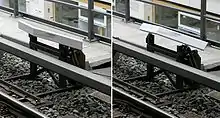
In the final version of the GWR system, the locomotives were fitted with a solenoid-operated valve into the vacuum train pipe, maintained in the closed position by a battery. At each distant signal, a long ramp was placed between the rails. This ramp consisted of a straight metal blade set edge-on, almost parallel to the direction of travel (the blade was slightly offset from parallel so in its fixed position it would not wear a groove into the locomotives' contact shoes), mounted on a wooden support. As the locomotive passed over the ramp, a sprung contact shoe beneath the locomotive was lifted and the battery circuit holding closed the brake valve was broken. In the case of a clear signal, current from a lineside battery energising the ramp (but at opposite polarity) passed to the locomotive through the contact and maintained the brake valve in the closed position, with the reversed-polarity current ringing a bell in the cab. To ensure that the mechanism had time to act when the locomotive was travelling at high speed, and the external current therefore supplied only for an instant, a "slow releasing relay" both extended the period of operation and supplemented the power from the external supply with current from the locomotive battery. Each distant signal had its own battery, operating at 12.5 V or more; the resistance if the power came directly from the controlling signal box was thought too great (the locomotive equipment required 500 mA). Instead, a 3 V circuit from a switch in the signal box operated a relay in the battery box. When the signal was at 'caution' or 'danger', the ramp battery was disconnected and so could not replace the locomotive's battery current: the brake valve solenoid would then be released causing air to be admitted to the vacuum train pipe via a siren which provided an audible warning as well as slowly applying the train brakes. The driver was then expected to cancel the warning (restoring the system to its normal state) and apply the brakes under his own control - if he did not the brake valve solenoid would remain open, causing all vacuum to be lost and the brakes to be fully applied after about 15 seconds. The warning was cancelled by the driver depressing a spring-laden toggle lever on the ATC apparatus in the cab; the key and circuitry was arranged so that it was the lever returning to its normal position after being depressed and not the depressing of the lever that reset the system - this was to prevent the system being overridden by drivers jamming the lever in the downward position or the lever accidentally becoming stuck in such a position. In normal use the locomotive battery was subject to constant drain holding closed the valve in the vacuum train pipe so to keep this to a minimum an automatic cut-off switch was incorporated which disconnected the battery when the locomotive was not in use and the vacuum in the train pipe had dropped away.[7]
It was possible for specially equipped GWR locomotives to operate over shared lines electrified on the third-rail principle (Smithfield Market, Paddington Suburban and Addison Road). At the entrance to the electrified sections a particular, high-profile contact ramp (4+1⁄2 in [110 mm] instead of the usual 2+1⁄2 in [64 mm]) raised the locomotive's contact shoe until it engaged with a ratchet on the frame. A corresponding raised ramp at the end of the electrified section released the ratchet. It was found, however, that the heavy traction current could interfere with the reliable operation of the on-board equipment when traversing these routes and it was for this reason that, in 1949, the otherwise "well proven" GWR system was not selected as the national standard (see below).[7][8]
Notwithstanding the heavy commitment of maintaining the lineside and locomotive batteries, the GWR installed the equipment on all its main lines. For many years, Western Region (successors to the GWR) locomotives were dual fitted with both GWR ATC and BR AWS system.
Strowger–Hudd system
By the 1930s, other railway companies, under pressure from the Ministry of Transport, were considering systems of their own. A non-contact method based on magnetic induction was preferred, to eliminate the problems caused by snowfall and day-to-day wear of the contacts which had been discovered in existing systems. The Strowger-Hudd system of Alfred Ernest Hudd (c. 1883 – 1958) used a pair of magnets, one a permanent magnet and one an electro-magnet, acting in sequence as the train passed over them. Hudd patented his invention and offered it for development to the Automatic Telephone Manufacturing Company of Liverpool (a subsidiary of the Strowger Automatic Telephone Exchange Company of Chicago).[9][10] It was tested by the Southern Railway, London & North Eastern Railway and the London, Midland & Scottish Railway but these trials came to nothing.
In 1948 Hudd, now working for the LMS, equipped the London, Tilbury and Southend line, a division of the LMS, with his system. It was successful and British Railways developed the mechanism further by providing a visual indication in the cab of the aspect of the last signal passed. In 1956, the Ministry of Transport evaluated the GWR, LTS and BR systems and selected the one developed by BR as standard for Britain's railways. This was in response to the Harrow & Wealdstone accident in 1952.[8]
Additional functions
AWS was later extended to give warnings for;[11]
- A colour light signal displaying a double yellow (steady or flashing), single yellow or red aspect
- A reduction in permissible speed
- A temporary or emergency speed restriction
- An automatic barrier crossing locally monitored (ABCL), an automatic open crossing locally monitored (AOCL), or an open crossing (OC).
AWS was based on a 1930 system developed by Alfred Ernest Hudd[9] and marketed as the "Strowger-Hudd" system. An earlier contact system, installed on the Great Western Railway since 1906 and known as automatic train control (ATC), was gradually supplanted by AWS within the Western Region of British Railways.
Network Rail
Network Rail (NR) AWS consists of:
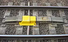
- A permanent magnet set centrally between the rails and usually positioned such that it is encountered 200 yd (183 m) before the signal to which it relates. The top of the magnet casing is nominally level with the running surface of the rails (to within 12 mm [1⁄2 in]).[12]
- An electromagnet between the rails (with opposite polarity to the permanent magnet) positioned after the permanent magnet. Again the top of the casing is nominally level with the running surface of the rails (to within 12 mm [1⁄2 in]).[12]
- A cab indicator that can show a black disk or a yellow and black "exploding" disk, known as the "AWS sunflower"
- A control unit that connects the system to the brakes on the train
- A driver's AWS acknowledgement button
- An AWS control panel
The system works on a set/reset principle.
When the signal is at 'clear' or green ("off"), the electromagnet is energised. As the train passes, the permanent magnet sets the system. A short time later, as the train moves forward, the electromagnet resets the system. Once so reset, a bell is sounded (a chime on newer stock) and the indicator is set to all black if it is not already so. No acknowledgement is required from the driver. The system must be reset within one second of being set, otherwise it behaves as for a warning indication.
An additional safeguard is included in the distant-signal control wiring to ensure the AWS "clear" indication is only given when the distant is proved "off" – mechanical semaphore distants have a contact in the electromagnet coil circuit closed only when the arm is raised or lowered by at least 27.5 degrees. Colour-light signals have a current sensing relay in the lamp lighting circuit to prove the signal alight, this is used in combination with the relay controlling the green aspect to energise the AWS electro-magnet. In a Solid State Interlocking the signal module has a "Green-Proved" output from its driver electronics that is used to energise the electromagnet.
When the distant signal is at 'caution' or yellow (on), the electro-magnet is de-energised. As the train passes, the permanent magnet sets the system. However, since the electromagnet is de-energised, the system is not reset. After the one-second delay within which the system can be reset, a horn warning is given until the driver acknowledges by pressing a plunger. If the driver fails to acknowledge the warning within 2.75 seconds, the brakes are automatically applied. If the driver does acknowledge the warning, the indicator disk changes to yellow and black, to remind the driver that they have acknowledged a warning. The yellow and black indication persists until the next signal and serves as a reminder between signals that the driver is proceeding under caution. The one-second delay before the horn sounds allows the system to operate correctly down to speeds as low as 1+3⁄4 mph (2.8 km/h). Below this speed, the caution horn warning will always be given, but it will be automatically cancelled when the electromagnet resets the system if the driver has not already done so. The display will indicate all black once the system resets itself.
The system is fail-safe since, in the event of a loss of power, only the electro-magnet is affected and therefore all trains passing will receive a warning. The system suffers one drawback in that on single track lines, the track equipment will set the AWS system on a train travelling in the opposite direction from that for which the track equipment is intended but not reset it as the electromagnet is encountered before the permanent magnet. To overcome this, a suppressor magnet may be installed in place of an ordinary permanent magnet. When energised, its suppressing coil diverts the magnetic flux from the permanent magnet so that no warning is received on the train. The suppressor magnet is fail-safe since loss of power will cause it to act like an ordinary permanent magnet. A cheaper alternative is the installation of a lineside sign that notifies the driver to cancel and ignore the warning. This sign is a blue square board with a white St Andrew's cross on it (or a yellow board with a black cross, if provided in conjunction with a temporary speed restriction).
With mechanical signalling, the AWS system was installed only at distant signals but, with multi-aspect signalling, it is fitted at all main line signals. All signal aspects, except green, cause the horn to sound and the indicator disc to change to yellow on black.
AWS equipment without electromagnets is fitted at locations where a caution signal is invariably required or where a temporary caution is needed (for example, a temporary speed restriction). This is a secondary advantage of the system because temporary AWS equipment need only contain a permanent magnet. No electrical connection or supply is needed. In this case, the warning indication in the cab will persist until the next green signal is encountered.
To verify that the on-train equipment is functioning correctly motive power depot exit lines are fitted with a 'Shed Test Inductor' that produces a warning indication for vehicles entering service. Due to the low speed used on such lines the size of the track equipment is reduced from that found on the operational network.

'Standard Strength' magnets are used everywhere except in DC third rail electrification areas and are painted yellow. The minimum field strength to operate the on-train equipment is 2 milliteslas (measured 125 mm [5 in] above the track equipment casing). Typical track equipment produces a field of 5 mT (measured under the same conditions). Shed Test Inductors typically produce a field of 2.5 mT (measured under the same conditions). Where DC third rail electrification is installed 'Extra Strength' magnets are fitted and are painted green. This is because the current in the third rail produces a magnetic field of its own which would swamp the 'Standard Strength' magnets.
AWS is provided at most main aspect signals on running lines, though there are some exceptions:[1]
- At through stations where the permitted speed is 30 mph (48 km/h) or less and the layout is complex. Where this occurs, these are called AWS gap areas.
- AWS magnets are not provided at semaphore stop signals (which can only display clear or stop).
- Where a line is not fitted with AWS magnets, it is shown in the Sectional Appendix.

Expansion of AWS application
- From 1971, an AWS permanent magnet was fitted ahead of the warning indicator where the permissible speed of a line dropped by more than a third.[13] This was a recommendation of the inquiry into the derailment at Morpeth on 7 May 1969.
- From 1977, a portable AWS permanent magnet was fitted ahead of the warning board on the approach to temporary speed restrictions (TSRs). This was a recommendation of the inquiry into the derailment at Nuneaton on 6 June 1975, which occurred when the driver missed a TSR warning board due to its lights being extinguished.
- From 1990, AWS permanent magnets were installed immediately ahead of certain 'high risk' stop signals, as a SPAD mitigation measure. This additional AWS magnet was suppressed when the associated signal showed a 'proceed' aspect. Since the introduction of the Train Protection & Warning System (TPWS) it is no longer current practice to use AWS for this purpose. SPAD indicators were also used.
Bi-directional operation
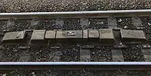
Because the permanent magnet is located in the centre of the track, it operates in both directions. The permanent magnet can be suppressed by an electric coil of suitable strength.
Where signals applying to opposing directions of travel on the same line are suitably positioned relative to each other (i.e. facing each other and about 400yds apart), common track equipment may be used, comprising an unsuppressed permanent magnet sandwiched between with both signals' electro-magnets.
Other countries
The BR AWS system is also used in:
- Northern Ireland Railways
- Hong Kong, MTR East Rail line (only used by intercity through trains; local trains operated by MTR Corporation use TBL as of 2012, enhanced with ATP/ATO[14] - due to be upgraded to CBTC by 2021[15])
- Queensland, Australia; sometimes enhanced with ATP. At the other extreme Queensland also provides a permanent magnet at the fixed distant signal of unattended crossing loops. This is also sometimes comes with AWS Signs.
- Adelaide, South Australia
- Taiwan Railways Administration EMU100, EMU200 series (used alongside ATS-SN/ATS-P, replaced with ATP in 2006)
- Experimental French system, half mechanical and half electrical (1913)[16]
- Liberia; One of the mining railways in this country had a more advanced AWS system that employed two or three magnets of either polarity and located near the rails to avoid the suppression problem. The system was therefore able to give more aspects than the BR version.
See also
References
- 1 2 3 4 5 6 7 "AWS & TPWS Handbook: Section 1.1.3 "The purpose of AWS"". RSSB. Archived from the original (PDF) on 5 December 2016. Retrieved 7 February 2017.
- ↑ Vanns (1997) p.129
- ↑ "The Inventor". The English Mechanic and World of Science. No. 448. 24 October 1873.
- ↑ US 1885061, George Kofler, "Automatic safety appliance for railway vehicles against overrunning of signals", published 25 October 1932
- ↑ US 843550, Frank Wyatt Prentice, "Electric Signaling System", published 5 February 1907
- ↑ Jackson, Alan A (1978). London's Local Railways. Newton Abbot, England: David & Charles. p. 99. ISBN 0-7153-7479-6.
- 1 2 Dymond, A. W. J. (10 March 1936). "The Automatic Train Control System of the Great Western Railway". Transactions. G. W. R. Swindon Engineering Society (206): 102, 115.
- 1 2 Wilson, G R S (12 June 1953). Report on the Double Collision which occurred on 8th October, 1952, at Harrow and Wealdstone Station in the London Midland Region British Railways. London: HM Stationery Office. pp. 25–29. OCLC 24689450.
- 1 2 "Alfred Ernest Hudd - Graces Guide". www.gracesguide.co.uk. Retrieved 6 August 2019.
- ↑ US 1599470, Alfred Ernest Hudd, "Railway Signalling System", issued 14 September 1926
- ↑ "AWS & TPWS Handbook: Section 1.4 "AWS indications and their meanings"". RSSB. Archived from the original (PDF) on 5 December 2016. Retrieved 24 September 2018.
- 1 2 AWS and TPWS Interface Requirements (3 ed.). London: Rail Safety and Standards Board. March 2018. p. 10.
- ↑ "Master Rulebook: Signals, hand signals, indicators and signs handbook. Section 7.2 "Warning indicators"" (PDF). Network Rail. Archived from the original (PDF) on 10 August 2018. Retrieved 7 March 2017.
- ↑ MTR East Rail Line: an intro. Checkerboard Hill. 15 March 2011. Retrieved 2 June 2013.
- ↑ "MTR awards East Rail upgrading contracts". Railway Gazette International. 21 December 2012. Retrieved 10 September 2017.
- ↑ "New Railway Signal Experiments". The Daily News. Perth, WA: National Library of Australia. 13 December 1913. p. 4 Edition: THIRD EDITION. Retrieved 2 August 2012.
Literature
- Dymond, A. W. J. (1948), "Forty years of automatic train control—the Great Western system", Journal of the Institution of Locomotive Engineers, Institution of Civil Engineers, 39 (207): 3–52, doi:10.1243/JILE_PROC_1949_039_007_02
- Currey, J. H. (1959), "Automatic train control — the British Railway system", Journal of the Institution of Locomotive Engineers, Institution of Civil Engineers, 49 (267): 104–126, doi:10.1243/JILE_PROC_1959_049_013_02
- Vanns, Michael A. (1997), An Illustrated History of Signalling, Ian Allan Publishing, ISBN 0-7110-2551-7
- Simmons, Jack; Biddle, Gordon (1997), The Oxford Companion to British Railway History, Oxford University Press, ISBN 0-19-211697-5
- Spowart, F. M. (March 2015). "AWS system - Introduction, Layout, Installation and Testing" (PDF). Archived from the original (PDF) on 31 December 2016. Retrieved 1 January 2018.
Further reading
- Cooper, Basil (December 1981 – January 1982). "You have been warned...". Rail Enthusiast. EMAP National Publications. pp. 12–13. ISSN 0262-561X. OCLC 49957965.